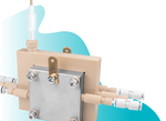
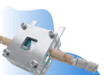
Standard GDE Flow Cell
Progress Your Testing in Gas-based Electrochemistry
Designed for method development and catalyst screening under continuous liquid-flow control
Specifications | In the Box | Gallery | Literature | Related Products | Technical Support
This standard GDE flow cell overcomes one of the central problems in gas-based electrochemistry: most reactant gases are poorly soluble in water, which starves the catalyst of reactant at the planar electrode. GDE cells feed gas through a porous electrode while liquid electrolyte flows continuously across the front, creates a three-phase boundary of gas, liquid, and catalyst meeting inside the electrodes pores with a shorter transport path and reaches current densities a standard H-cell simply cannot.
This GDE flow cell can be used with a range of gas diffusion electrodes. The cell design has a more forgiving liquid gap than our advanced compact cell, as well as being easy to assemble and align. The continuously circulating liquid electrolyte chambers remove reaction products in real time and suppresses competing hydrogen evolution, while the S-shaped geometry delivers gas efficiently to a GDE over a 1 cm x 1 cm working area. This cell is well suited to method development, catalyst screening and applications such as:
- Carbon dioxide reduction reaction (CO2RR): The catalytical conversion of carbon dioxide into value-added chemicals, syngas, or green fuels (like ethylene or formic acid)
- Nitrogen reduction reaction (NRR): Nitrogen reduction reaction for nitrogen containing fertilizers production
- Oxygen reduction reaction (ORR): Hydrogen peroxide electrosynthesis for water treatment and environmental remediation

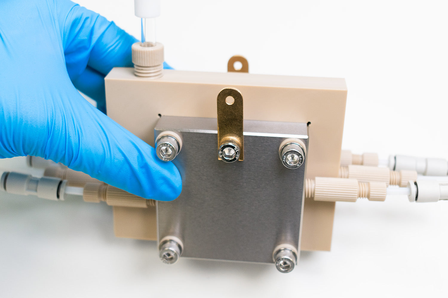
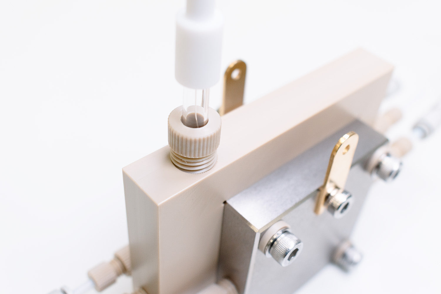
PEEK Chambers & Pt Plates
Prevents corrosion & handles
larger current collection

Aqueous Flow Cells
Flowing electrolyte chamber for continuous liquid products removal

Three-phase Boundary Design
To prevent mass-transport
limitations

Larger Liquid Gap
Easy to align in method
development & catalyst screening
Specifications
| Cathode and Anode Field Plate/ Chamber Material | Titanium- TA2 (with Serpent Flow Fields) |
|---|---|
| Cathode and Anode Field Plate/ Chamber Dimensions | 60 mm x 60 mm x 19 mm (H x W x T) |
| GDE Working Area | S-shaped, 1 cm x 1 cm, 1.5 mm width and depth |
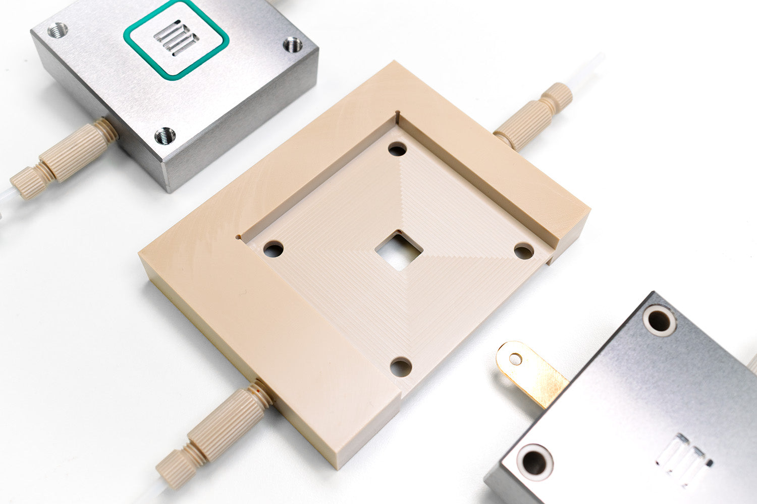
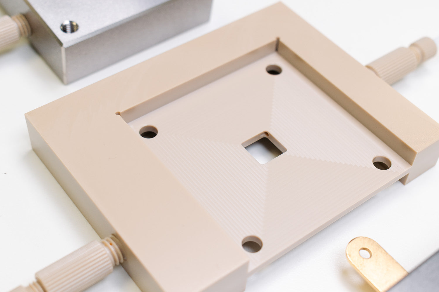
| Catholyte Chamber Material | PEEK (1 cm x 1 cm window, 3 mm depth) |
| Spacing Between Cathode and Anode Chambers | < 3.5mm |
| Reference Electrode | Ag/AgCl, Standard 6 mm |
| Gaskets | FKM and PTFE (52 mm x 52 mm, see thickness and window sizes below) |
| FKM Gasket Thickness (15 mm x 15 mm window) | 0.2 mm, 0.3 mm, 0.8 mm, 1.0 mm |
| FKM Gasket Thickness (10 mm x 10 mm window) | 0.2 mm |
| PTFE Gasket Thickness (15 mm x 15 mm window) | 0.2 mm, 0.25 mm |
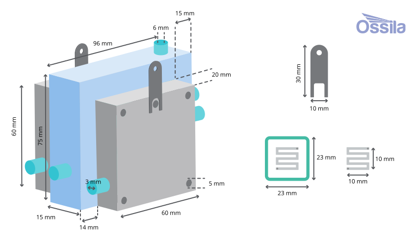
Note: The Standard GDE Flow Cell can be used as zero-gap MEA electrolyzer once the flow field is removed.
What is a Gas Diffusion Electrode?
The gas diffusion electrode is a working electrode built from three layers that work together to sustain this boundary. A porous, conductive support (gas diffusion layer) of either carbon paper, carbon cloth, or metal mesh gives the electrode mechanical strength while letting gas through and keeping electrolyte out. A hydrophobic microporous layer, typically carbon black mixed with PTFE, stops electrolyte from flooding into the gas pores. A catalyst layer on top of that platinum, silver, copper, or another catalyst depending on the target reaction, where the electrochemical conversion actually happens.
Our Standard GDE flow cell can accommodate many suitable GDEs, with a working area of 1 cm x 1 cm.
In the Box*
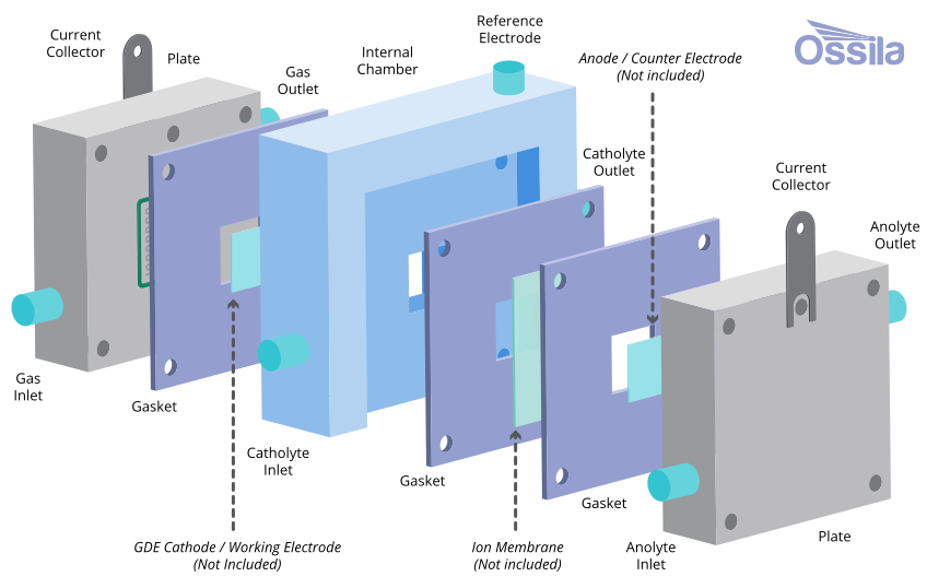
- Titanium cathode/anode chambers
- PEEK chamber
- Gaskets (PTFE & FKM)
- PTFE tube
- Tube cutter
- Contact collector Leads
- Copper tape
- PTFE gas & electrode stoppers
- Gas & electrode secure screws
- Assorted O-rings
- Screws & washers
- Gas locks
- PTFE tape
- Ag/AgCl reference electrode
*Working electrode or membrane is not included as standard accessories with the cell. You will need to source or fabricate a GDE compatible with your catalyst system, plus a suitable ion-exchange membrane to separate the two compartments.
Product Gallery
Literature
- D. Wakerley et al. (2022), Gas diffusion electrodes, reactor designs and key metrics of low-temperature CO2 electrolysers, Nat. Energy, 7, 130–143; DOI: 10.1038/s41560-021-00973-9.
- K. Liu et al. (2019), Introductory Guide to Assembling and Operating Gas Diffusion Electrodes for Electrochemical CO2 Reduction, ACS Energy Lett., 4 (3), 639–643; DOI: 10.1021/acsenergylett.9b00137.
- A. Soni et al. (2025), Accelerated optimization of gas diffusion electrodes for CO2 electrolyzers, Matter, 9, 102519; DOI: 10.1016/j.matt.2025.102519.
Related Products