
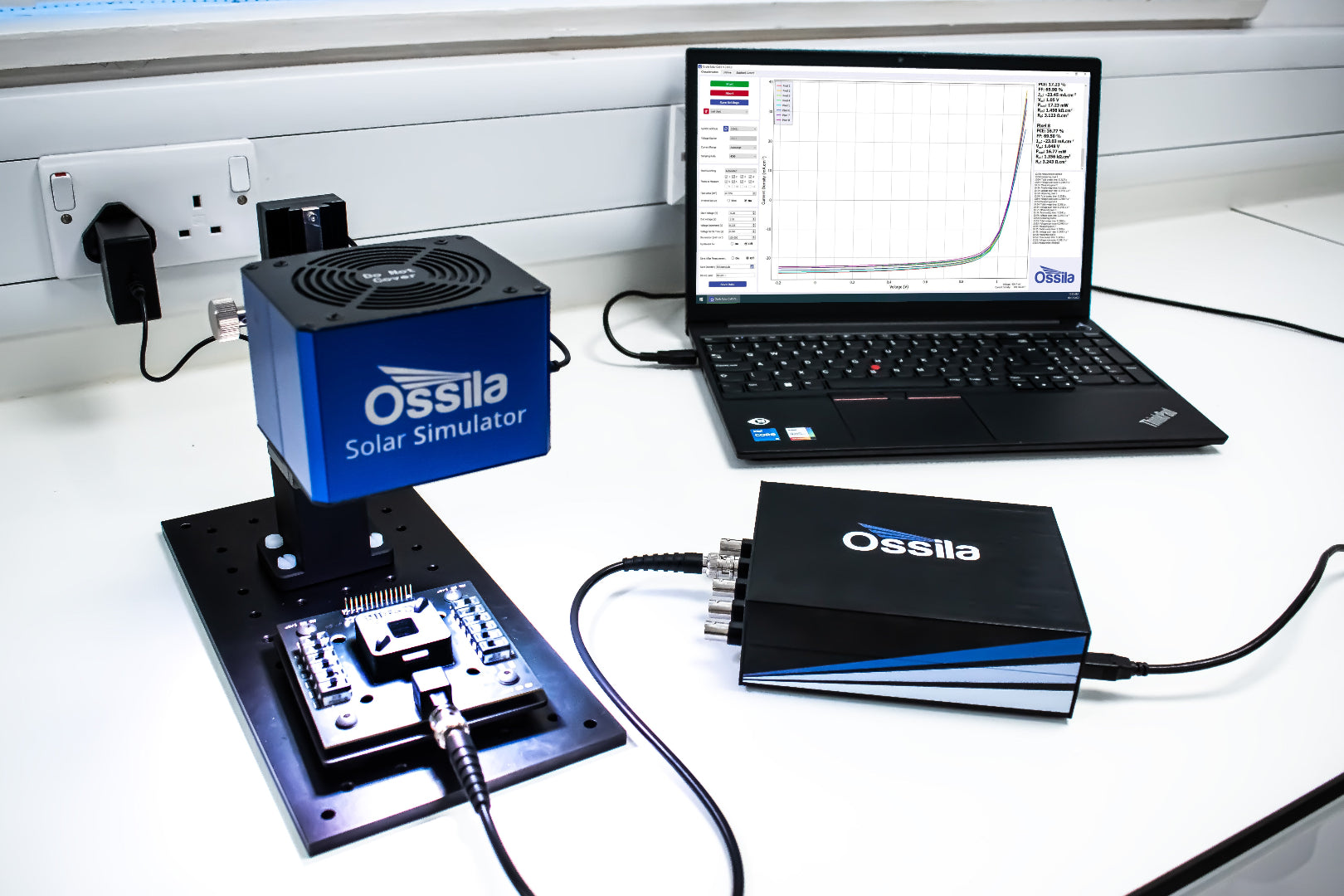
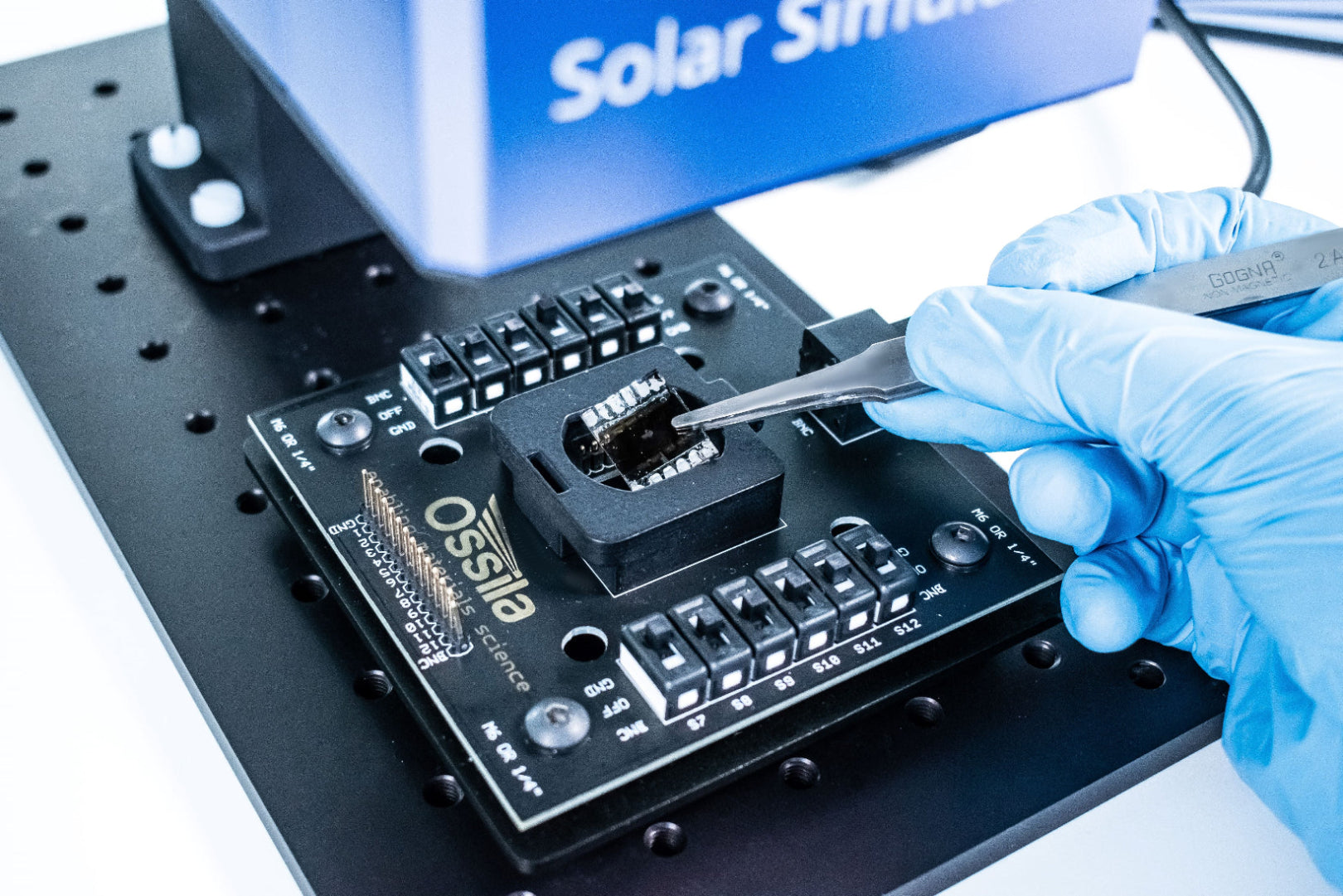
Complete Testing Setup for Flexible Solar Cell Characterization
A solar simulator, source measure unit and the reference solar cell available at a discounted price
Overview | Specifications | Software | Features | Gallery | In the Box | Resources and Support
Take control of your solar cell testing with a complete solution for fast, reliable device characterization. The kit includes:
- A carefully calibrated LED solar simulator which delivers a high quality spectrum. Achieve excellent spectral match, spatial uniformity, and temporal uniformity for reliable testing.
- A dual-output source measure unit for full control over your testing parameters. Customize measurements and capture accurate
I–V curves and performance metrics with confidence.
Use the source measure unit and solar simulator independently or together to suit your exact experimental requirements.
All of the Solar Cell Testing Kits include the Ossila Reference Solar Cell. This reference photodiode allows you to monitor and follow solar simulator irradiance, verifying a consistent output.

Rapid Characterization
Build custom measurements of device
metrics with flexible software
Great Value & a Long Lifetime
Use reliably for 10,000 hours
across multiple experiments
Measure Device Stability
Track key device properties over repeated current-voltage measurements
Customize the Spectral Output
Individual LED power control
across 350 nm – 1000 nm
Specifications
Solar Simulator
The improved solar simulator has slightly increased spectral coverage across the visible spectrum, and reduced spectral deviation compared to previous versions, while still maintaining 1 Sun Irradiance between 380 – 1000 nm.
While both version solar simulators achieve AAA classification over a 15 mm area, the new solar simulator (released January 2026) has a marginally improved spectral match. Previous classification graphs (for Solar Simulators purchased before 2025) can be found on our Classification Data page.
| Spectral Match | A |
|---|---|
| Spatial Uniformity (over 15 mm diameter area) | A |
| Spatial Uniformity (over 25 mm diameter area) | B |
| Spatial Uniformity (over 32 mm diameter area) | C |
| Temporal Instability | A |

| Type | LED-based, steady-state |
|---|---|
| Spectral Deviation | <70% |
| Spectral Coverage | >80% |
| Working Distance | 8.5 cm |
| Irradiance* | 1000 W/m2 |
| Maximum Lamp Time | 10000 hours |
| Lamp Dimensions (L x W x H) | 10.5 cm x 9.0 cm x 8.0 cm |
| Weight | 600 g |
* +/- 5% at working distance and calibration temperature.

Source Measure Unit
Voltage Source
| Range | Accuracy | Precision | Resolution |
|---|---|---|---|
| ±10 V | 10 mV | 333 µV | 170 µV |
Voltage Measure
| Range | Accuracy | Precision | Resolution |
|---|---|---|---|
| ±10V | 10 mV | 50 µV | 10 µV |
Current Measure
| Range | Max Current | Accuracy1 | Precision2 | Resolution | Burden |
|---|---|---|---|---|---|
| 1 | ±200 mA | ±500 µA | 10 µA | 1 µA | <20 mV |
| 2 | ±20 mA | ±10 µA | 1 µA | 100 nA | <20 mV |
| 3 | ±2 mA | ±1 µA | 100 nA | 10 nA | <20 mV |
| 4 | ±200 µA | ±100 nA | 10 nA | 1 nA | <20 mV |
| 5 | ±20 µA | ±10 nA | 1 nA | 0.1nA | <20 mV |
1Accuracy has been measured at the maximum current of the range.
2Precision has been measured at the highest OSR (9).
Voltage Meter
| Range | Accuracy | Precision | Resolution |
|---|---|---|---|
| ±10 V | 10 mV | 50 µV | 10 µV |
Please see the Source Measure Unit product page for full specifications.

Equipment Specifications
| Compatible Substrates | 20 mm x 15 mm (T2002B2-G2009A1 or T2002G2-G2009A1) 25 mm x 25 mm (T2002E2-G2009A1 or T2002G2-G2009A1) |
|---|---|
| Lamp Dimensions (L x W x H) | 105 mm x 90 mm x 80 mm (4.31" x 3.54" x 3.15") |
| Source Measure Unit Dimensions (L x W x H) | 185 mm x 125 mm x 55 mm (7.28" x 4.92" x 2.17") |
Software
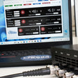
Solar Cell I-V
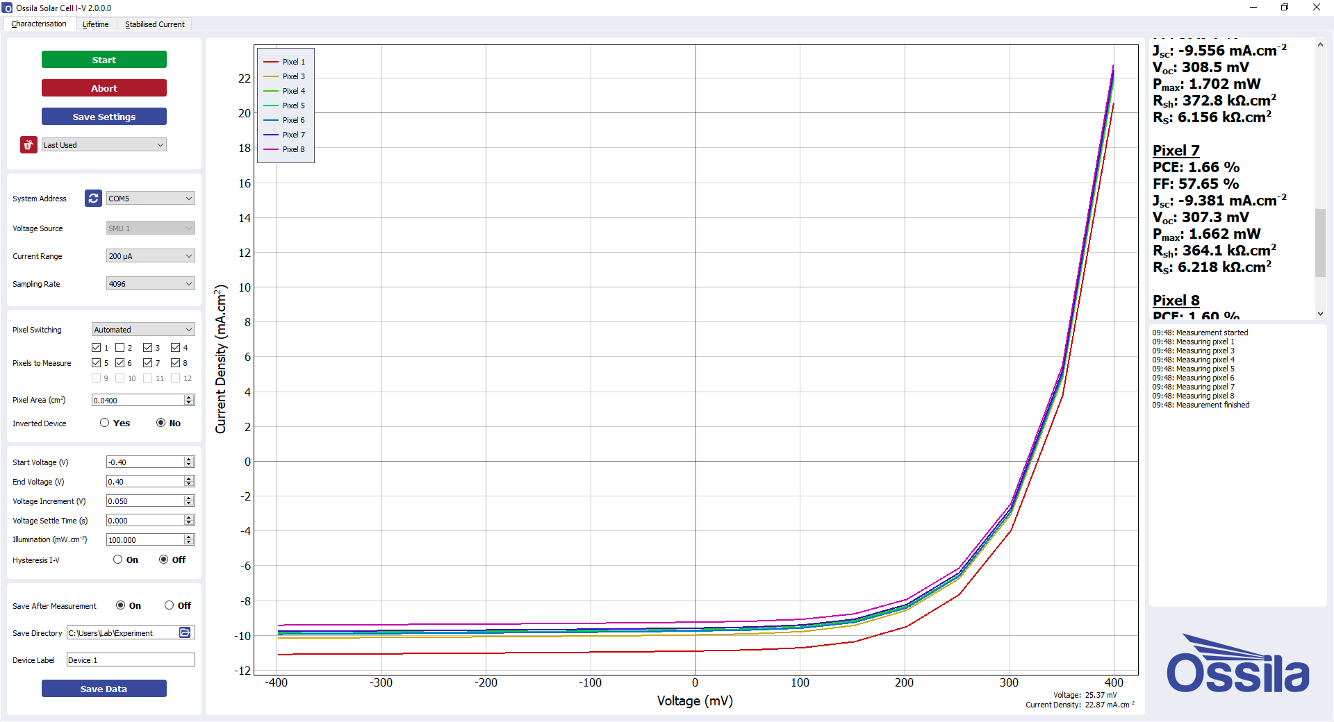
With the PC software, you can:
- Perform current-voltage measurements anywhere between -10 V and 10 V.
- Take high resolution measurements, with voltage increments as low as 170 µV.
- Manage the experiment more directly, with custom settle times between applying voltage and measuring current.
- Measure device hysteresis by perform consecutive measurements in forwards and backward directions.
The software has 4 measurement tabs: Solar Cell Characterization, Stabilized Current Output, Solar Lifetime Measurement, and Maximum Power Point Tracking. 'Characterization' performs I-V measurements and calculates the important device properties, the 'Stabilized Current' tab allows you to determine how the current output of your device evolves over time using, and the 'Lifetime' tab enables you to track key device properties (PCE, FF, Jsc, Voc) over an extended time by performing periodic I-V characterization. Between measurements the solar cell can be held at open-circuit, short-circuit, or maximum power. The 'Maximum Power Point' tab tracks the maximum power point over time, as well as the current density Jmp and operating voltage Vmp.
Software Requirements
| Operating System | Windows 11 (64-bit) |
|---|---|
| CPU | Dual Core 2 GHz |
| RAM | 4 GB |
| Available Hard Drive Space | 233 MB |
| Monitor Resolution | 1680 x 1050 |
| Connectivity | USB 2.0, or Ethernet (requires DHCP) |
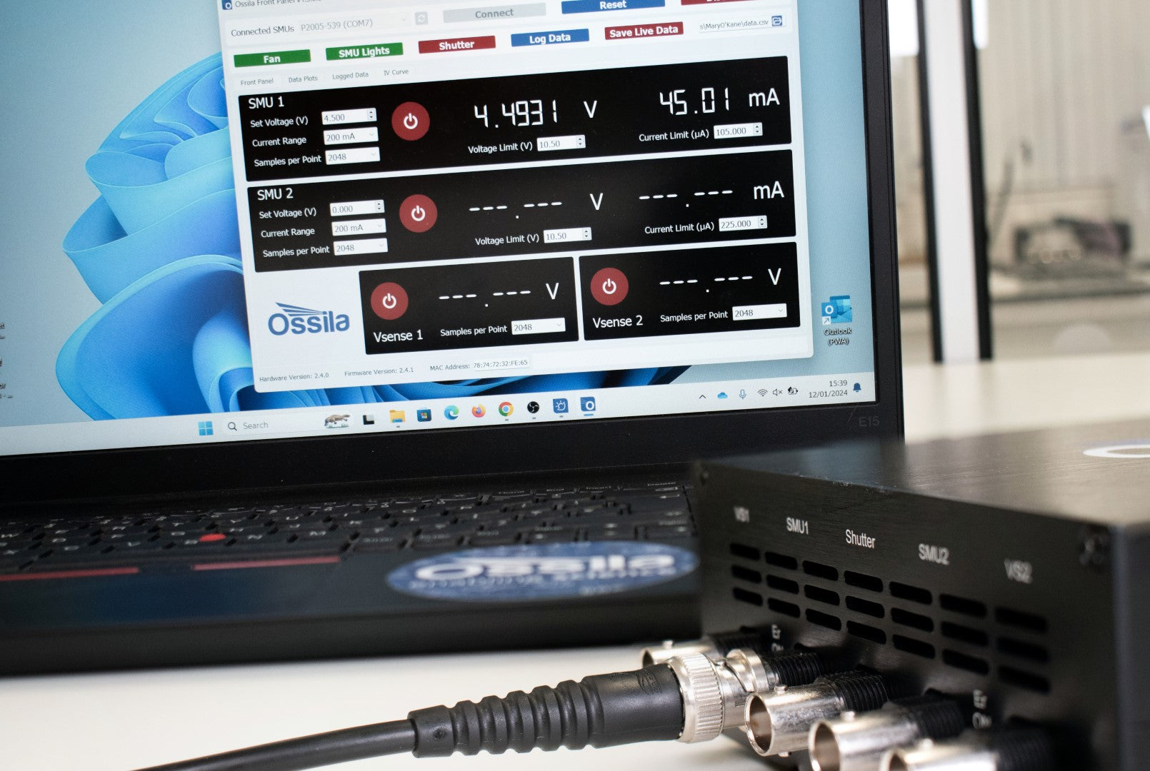
Learn about the Source Measure Unit Front Panel software.
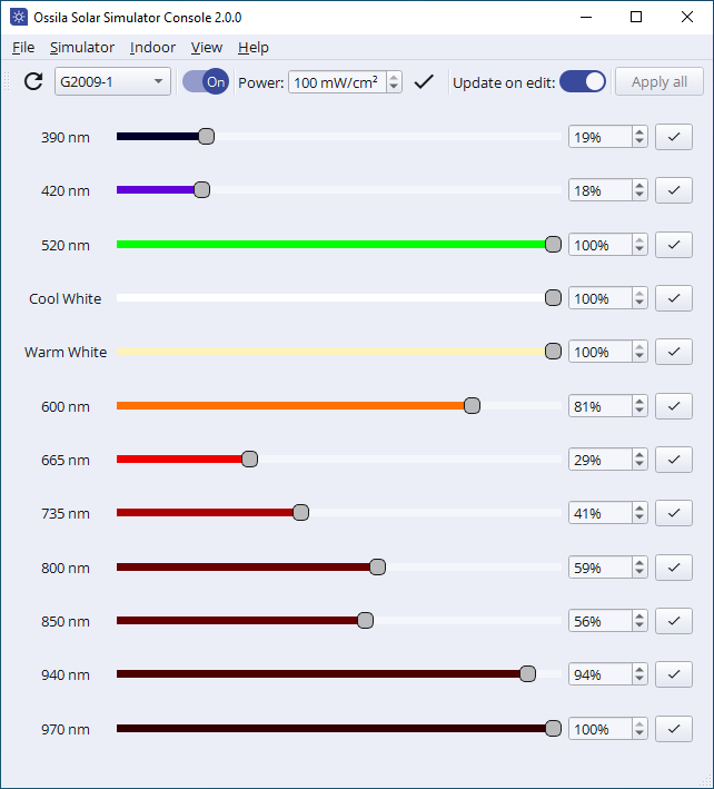
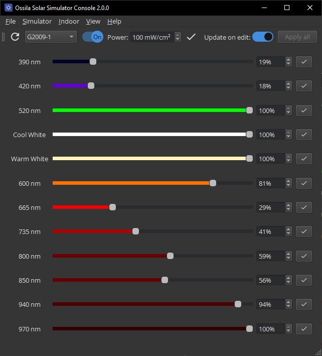
Solar Simulator Console
Control and customize the output of your LED solar simulator. You can choose the overall power level or control each LED individually to tailor the output to your specific requirements. The user-friendly software can be installed on as many PCs as you want and you can access future updates for free.
Software Requirements
| Operating System | Windows 11 (64-bit) |
|---|---|
| CPU | Dual Core 2 GHz |
| RAM | 4 GB |
| Available Hard Drive Space | 152 MB |
| Monitor Resolution | 1440 x 960 |
| Connectivity | USB |
Complete, Reliable Characterization
Complete Measurement Setup
Everything you need for reliable photovoltaic characterization. Perform I-V sweeps to find key device performance metrics, run lifetime measurements for degradation studies, or use as a soaking system to precondition cells. Fine-tune testing parameters and build bespoke measurement routines that match your exact needs.
Five Independent Channels
Output voltage and simultaneously measure current and/or voltage using the two SMU channels, while two additional voltmeter channels let you monitor voltage from external components. Plus, you can integrate external control or automation into your workflow with the shutter/trigger channel.
Adapt the Spectral Output
Reliably and accurately mimic the solar spectrum in your photovoltaic research with a calibrated array of light emitting diodes. Change the total irradiance output or control the power output of each LED individually. With a tunable spectrum, align your testing with specific lighting spectrum conditions, even to test indoor photovoltaics according to newly defined standards.
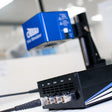
Manual Solar Cell Testing Kit Gallery


In the Box
- LED Solar Simulator
- Source Measure Unit
- Test board
- Reference solar cell
- USB Driver with calibration certificate & QC test data
Resources and Support
 Analyzing and Improving Low Device Metrics: FF, VOC and JSC
Anaylzing key device metrics such as fill factor (FF), open-circuit voltage (VOC), and power conversion efficiency (PCE), can help you find potential issues with your solar cell devices
Read more...