
Dual Channel System for Versatile I-V Measurements
Source voltage and measure voltage & current reliably and easily
Overview | Specifications | Features | Gallery | Software | In the Box | Related Products | Resources and Support
Designed for scientists and engineers working on the next generation of electronic devices. Measure the I-V characteristics of many devices including photovoltaics, LEDs and OLEDs, transistors, and more. A source measure unit (also known as a source meter or SMU) is a tool that can power your electronics and measure their performance at the same time. It combines the capabilities of several instruments into one compact package, saving bench space, time, and programming issues.
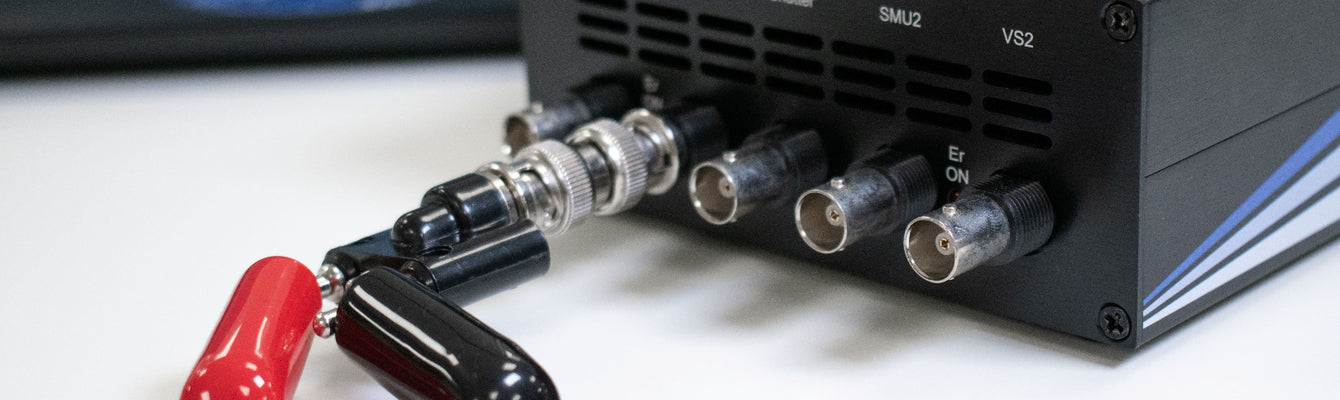
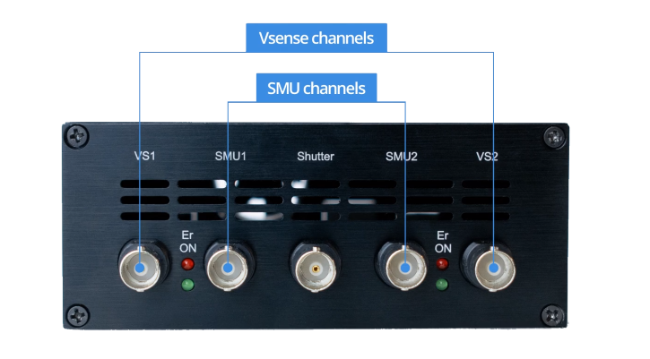
The Ossila Source Measure Unit can source voltage while simultaneously measuring current and voltage, performing the role of multiple components in one synchronized unit. The dual channel system contains four instruments on one board: two SMUs (voltage source, current sense) and two precision voltage sense channels. Plus, you can use the general-purpose shutter/trigger to send and receive control signals to and from other instruments.
For a simple solution that does the work for you, take a look at our solar cell and LED test systems, which have been purpose-built to streamline your research with intuitive software and no need for programming knowledge. Alternatively, for a complete set up, consider the electrical characterization system, which includes a probe station and set of a micromanipulators.

Two-Year Warranty
Buy with confidence
Compact
Space-saving design
Wide Current Range
Measure 10 nA to 200 mA
Free Software
Easily controllable
The Source Measure Unit is a professional alternative to old-fashioned and outdated bench top source-measure units at a fraction of cost. Ossila's product was thoroughly tested by us, it had to compete with state-of-art devices and to our surprise it won the race in all categories: precise PV measurements, networking capabilities, flexibility of programming language and smooth operation in pretty tough chemical/material science laboratories. The Ossila team has delivered a game changer for all of the PV community.
Adam Surmiak, PhD Student in Excitonic Systems for Solar Energy Conversion, Monash University
Why Use A Source Measure Unit?
Easy To Control: SMUs are easily programmable and user-friendly. This streamlines the measurement process, compared to managing separate inputs and outputs.
Fast Measurement Speed and Increased Accuracy: Integrating multiple functions into one system reduces measurement time. Combined with minimal signal loss and measurement errors, this leads to more accurate measurements.
Compact and Budget-Friendly: With fewer systems involved, choosing an SMU saves money and lab space.
Handling Negative Voltages: Some electronic devices need to be tested under both positive and negative voltages. Source measure units can do this easily, without resetting the system or rearranging the setup.
Multiple Channels: The multiple channels in an SMU allow complex measurements to be taken.
Multiple Measurements: SMUs can take multiple measurements in rapid succession. This is great for obtaining quick snapshots of devices (e.g. I-V curves) or for measuring dynamic behavior.
Can You Use Individual Components Instead?
You could potentially build a system that can do what a source measure unit can do, with moderate accuracy, using individual components. To do this, you would need to combine:

- A benchtop power supply to output voltage
- Several good quality multimeters
- One to measure voltage
- One to measure the current
- An external data control center, such as a computer, to coordinate measurement
However, if you are combining equipment in this way, there are significant drawbacks to consider:
- It is difficult to programme
- The cost of individual components can add up quickly
- You must rearrange the system to measure both positive and negative voltages
- Human error can be a big issue
- Combining multiple components introduces a delay
The Ossila Source Measure Unit combines these components into one convenient unit so you can conduct different measurements for different samples with one piece of equipment.
Applications
Source measure units can measure and characterize many electronic devices and material properties. Some applications include:
- LED and OLED characterization
- Solar cell I-V curves and stability measurements
- Measuring transistor properties, such as current gain
- Measuring battery discharge rates (V Sense channels only)
- Testing electronics components
- Testing materials by measuring conductivity, leakage currents, and other properties
Specifications
Source Measure Units (SMU 1 & SMU 2)
The SMUs output a voltage and then measure both the voltage and current. The output voltage is always measured on the output to the BNC, rather than assuming it is at the set voltage. This is to account for any load effects, for example, short circuiting the output, or low impedance causing a small drop in voltage. Each source measure unit has multiple current ranges, so that you can measure both large and small currents with accuracy.
Voltage Source Specifications
| Range | Accuracy | Precision | Resolution |
|---|---|---|---|
| ±10 V | 10 mV | 333 µV | 170 µV |
Voltage Measure Specifications
| Range | Accuracy | Precision | Resolution |
|---|---|---|---|
| ±10V | 10 mV | 50 µV | 10 µV |
Current Measure Specifications
| Range | Max Current | Accuracy1 | Precision2 | Resolution | Burden |
|---|---|---|---|---|---|
| 1 | ±200 mA | ±500 µA | 10 µA | 1 µA | <20 mV |
| 2 | ±20 mA | ±10 µA | 1 µA | 100 nA | <20 mV |
| 3 | ±2 mA | ±1 µA | 100 nA | 10 nA | <20 mV |
| 4 | ±200 µA | ±100 nA | 10 nA | 1 nA | <20 mV |
| 5 | ±20 µA | ±10 nA | 1 nA | 0.1nA | <20 mV |
1Accuracy has been measured at the maximum current of the range.
2Precision has been measured at the highest OSR (9).
Precision Voltage Meter Specifications (Vsense 1 and Vsense 2)
The voltage meters are designed to accurately sense small voltages while also having a wide dynamic range (±10 V).
| Range | Accuracy | Precision | Resolution |
|---|---|---|---|
| ±10 V | 10 mV | 50 µV | 10 µV |
Shutter/Trigger
The Shutter/Trigger can be used either as an input or an output. It can be used to send a trigger signal to other instruments or configured to wait for a trigger from other instruments. The voltage level of this BNC is 5 V because any higher may cause damage to the port.
Source Measure Unit Features

Five Independent Channels
Features dual source measure and voltmeter channels. Two SMU channels output voltage while measuring current and/or voltage, and two separate voltage measurement channels measure voltage sourced by external components. The shutter/trigger channel allows external control and programming.
Wide Voltage and Current Range
Choose between five separate current ranges to suit your experimental needs. Plus, 10 different speed/resolution settings. Take measurements at DC or low frequency over a voltage range from -10 V to +10 V, with a current flow from 10 nano-amps (nA) to 200 milliamps (mA).
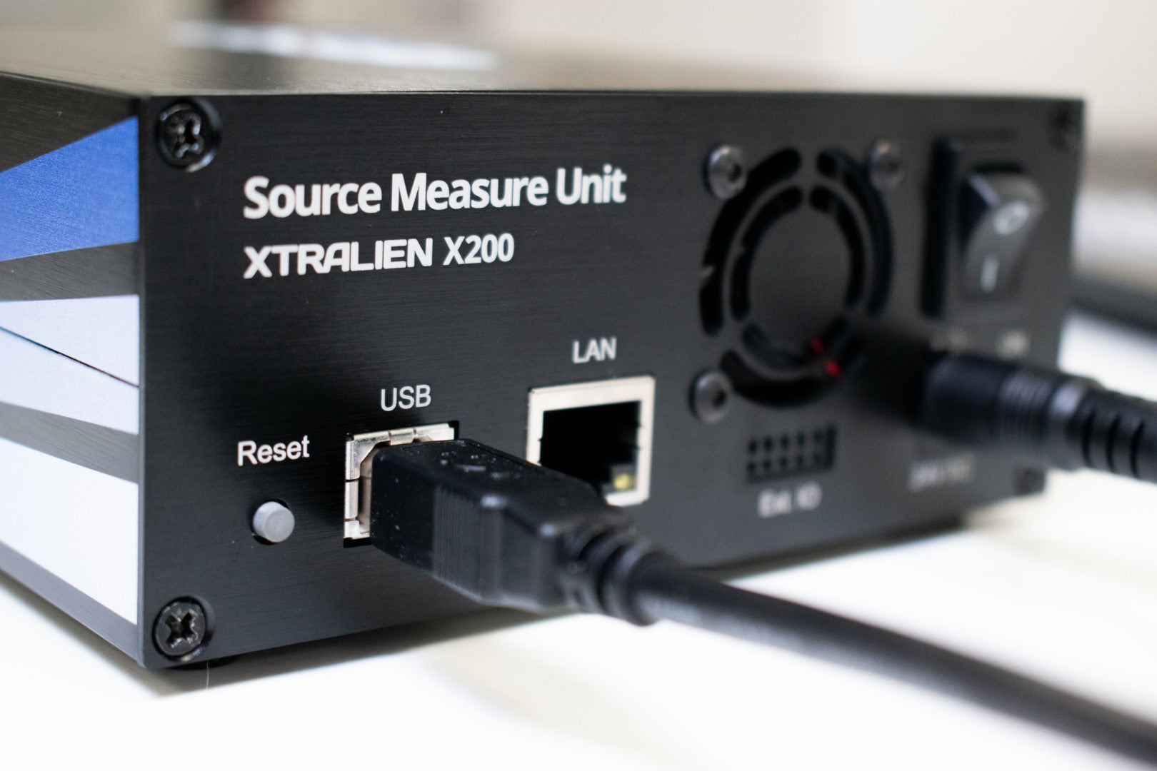
Flexible and Scalable Communication
Expand your experimental capabilities by connecting the source measure unit via USB, or use several units at the same time via Ethernet connection.
Choose Your Preferred Programming Language
The user-friendly design works with almost any programming language. Common compatible languages include Python, MATLAB, Java, C/C++, and more.
Source Measure Unit Gallery


Software
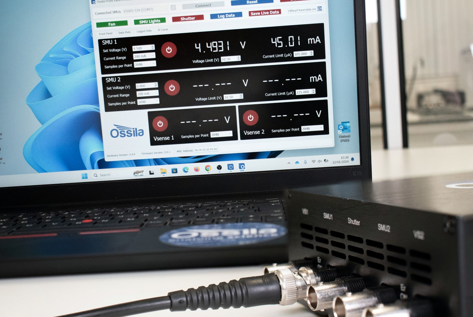
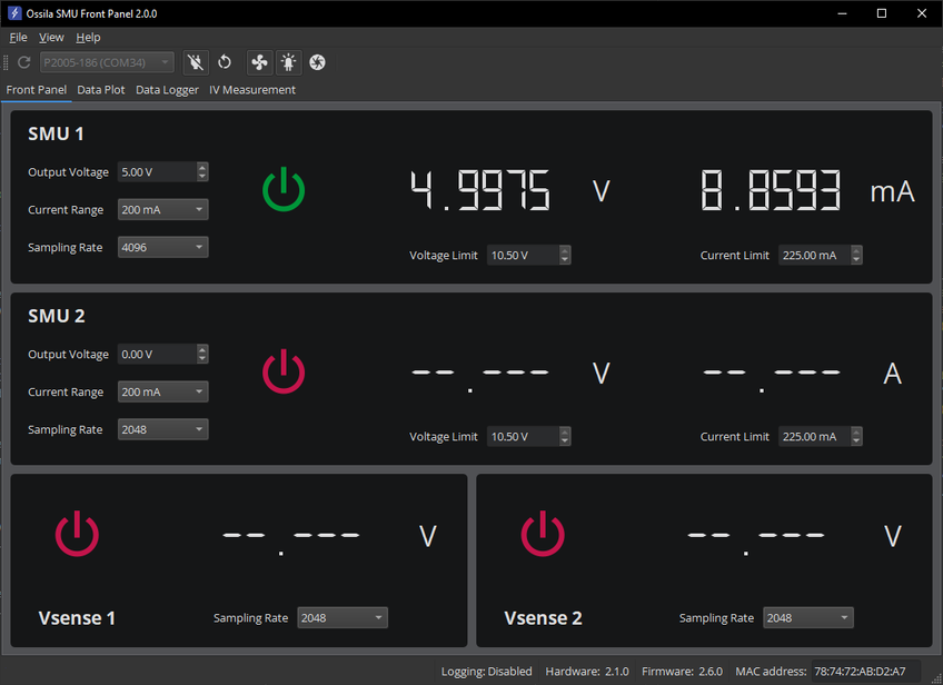
The Ossila Source Measure Unit includes Front Panel software that enables you to start taking measurements as quickly as possible. With the program you can:
- Control each SMU and Vsense channel independently, allowing you to perform many of the most common electrical measurements.
- Set voltage and measure current with two independent SMU channels (voltage source, current sense).
- Quickly and accurately measure voltages with the two Vsense channels.
- Easily set sampling rates for the SMUs and Vsense channels via the interface.
- Save your data as a portable spreadsheet (.csv) file or a text (.txt) file for analysis with your favorite software package.
Other Software
We also have software for performing specific measurements with the Ossila Source Measure Unit. These can be downloaded for free from our software and drivers page. The currently available measurements are:
- I-V curves
- Solar cell characterization and lifetime
- Four-point probe sheet resistance
Programming Languages
The user-friendly design works with almost any programming language. Common languages that can be used to interface to it are:
Software Requirements
| Operating System | Windows 11 (64-bit) |
|---|---|
| CPU | Dual Core 2 GHz |
| RAM | 4 GB |
| Available Drive Space | 201 MB |
| Connectivity | USB 2.0, or Ethernet (requires DHCP) |
Additional Specifications

Physical Specifications
| Computer Connectivity | USB-B and Ethernet |
|---|---|
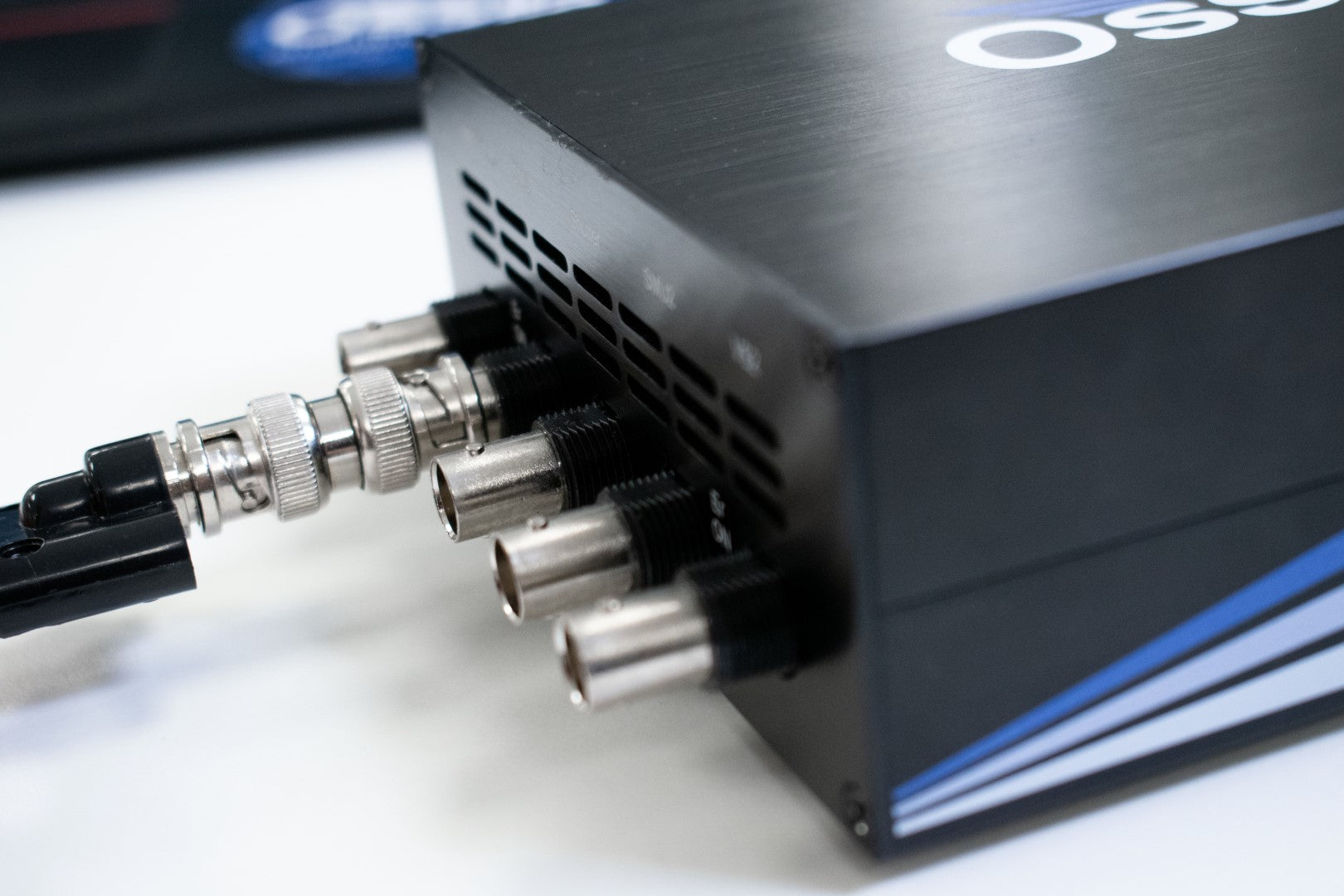
| Measurement Connections | BNC connector |
| Dimensions (L x W x H) | 185 mm x 125 mm x 55 mm (7.28" x 4.92" x 2.17") |
Manuals
![]() Source Measure Unit user manual
Source Measure Unit user manual
![]() Source Measure Unit programming documentation
Source Measure Unit programming documentation
In the Box
The standard items included with the Ossila Source Measure Unit are:
- Source measure unit
- 24 V / 2 A DC power adapter
- USB-B cable
- User manual and QC data
- USB drivers and Front Panel software installer
- USB Driver with QC test data
Related Products

Electrical Characterization System
The complete electrical characterization kit. Includes a probe station, four micromanipulators, a source measure unit, a set of tungsten probe tips, two differential interfaces, and a set of cables.
Take control of your solar cell measurements with a simple and reliable system for PV characterization. The free PC software automatically calculates key properties of solar cells from the measured I-V curves.
A complete solution for LED characterization and lifetime measurements. Perform I-V measurements, calculate the current and power efficiencies, and set a constant voltage and measure performance over an extended time.
If you are looking for a flexible solution for OEM applications, the OEM Source Measure Unit Set includes 5 source measure unit PCBs for a discounted price.
Resources and Support
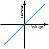 I-V Curves: A Guide to Measurement
An I-V curve (short for 'current-voltage characteristic curve'), is a graphical representation of the relationship between the voltage applied across an electrical device and the current flowing through it.
Read more...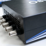 SMU Quickstart Guide
The latest quick start guide for the Ossila Source Measure Unit, to set up your device
Read more...