
Manual Micromanipulators for Precise, Repeatable Control
Equipped with a 20 μm tungsten probe as standard to make stable electrical contact
Overview | Choosing Positioning Resolution? | Specifications | Reducing Leakage Current and Resistance
Features | Gallery | In the Box | Accessories | Compatible Adapters | Resources and Support
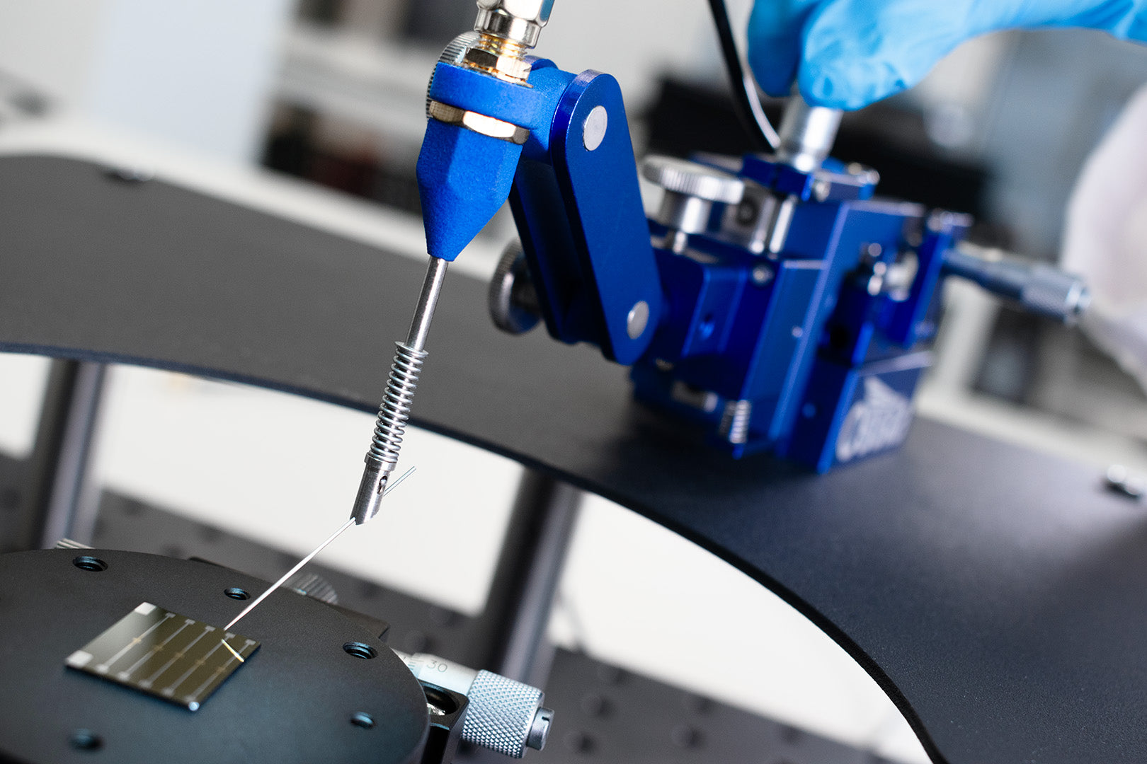
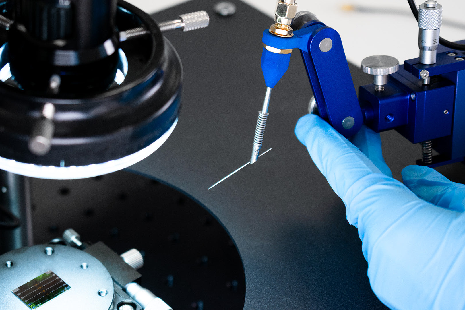
Reliably control tools or probes at a microscopic scale with the Ossila Micromanipulator. Move, test, and interact with incredibly small objects such as electronic components, 2D materials, or even single cells. Acting as an extenstion of your hands under a microscope, these micromanipulators give you smooth, steady, and repeatable control over tools that would otherwise be impossible to position accurately. With an Ossila micromanipulator you get:
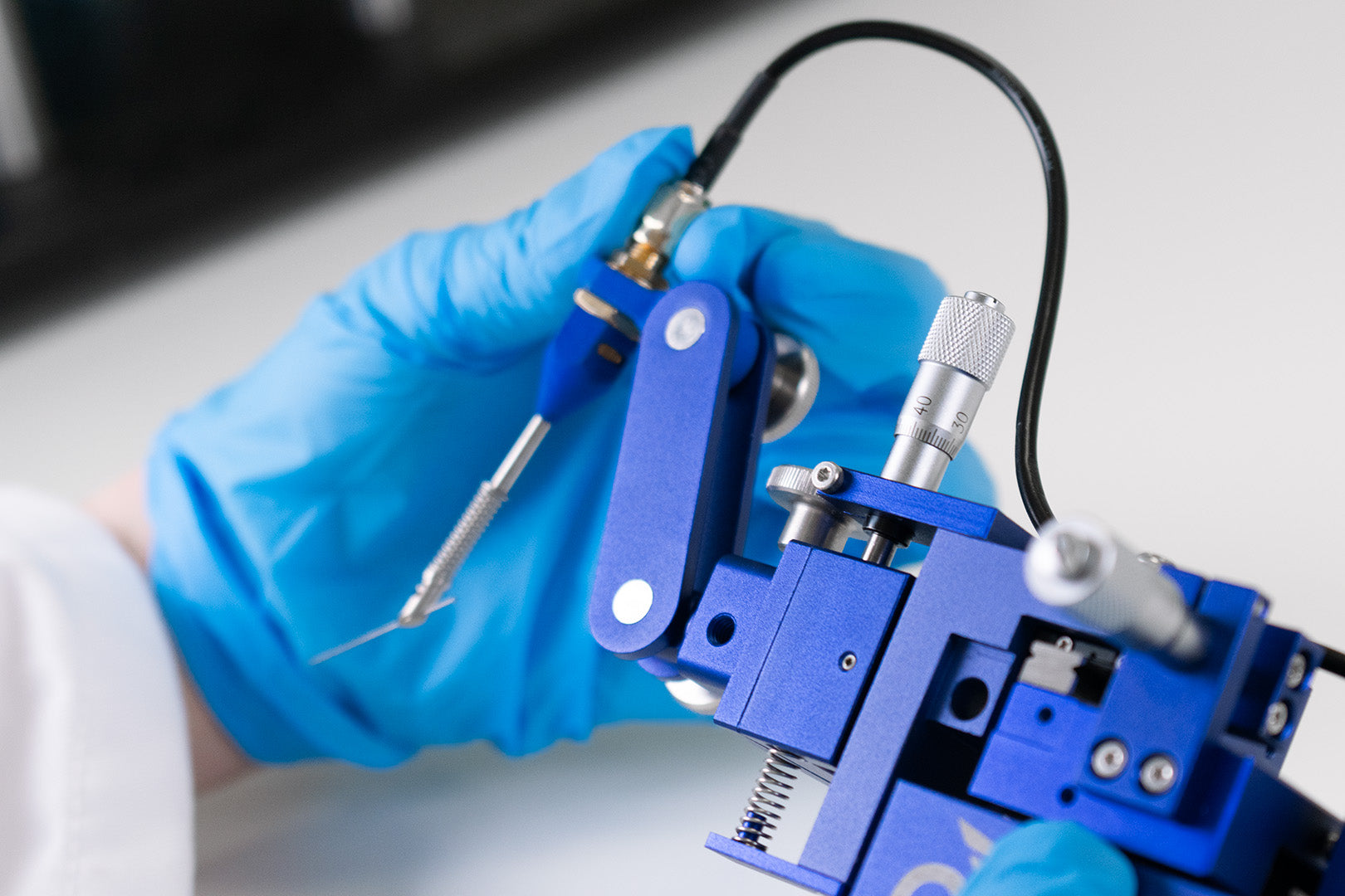
Perform delicate probe alignment and make stable electrical contact with the included 20 μm tungsten probe. Precision linear bearings ensure smooth, repeatable motion and micron-level accuracy down to 4 μm with minimal backlash or drift. For more sensitive experiments, the fine-pitch micrometer allows probe adjustments by as little as 2 μm.
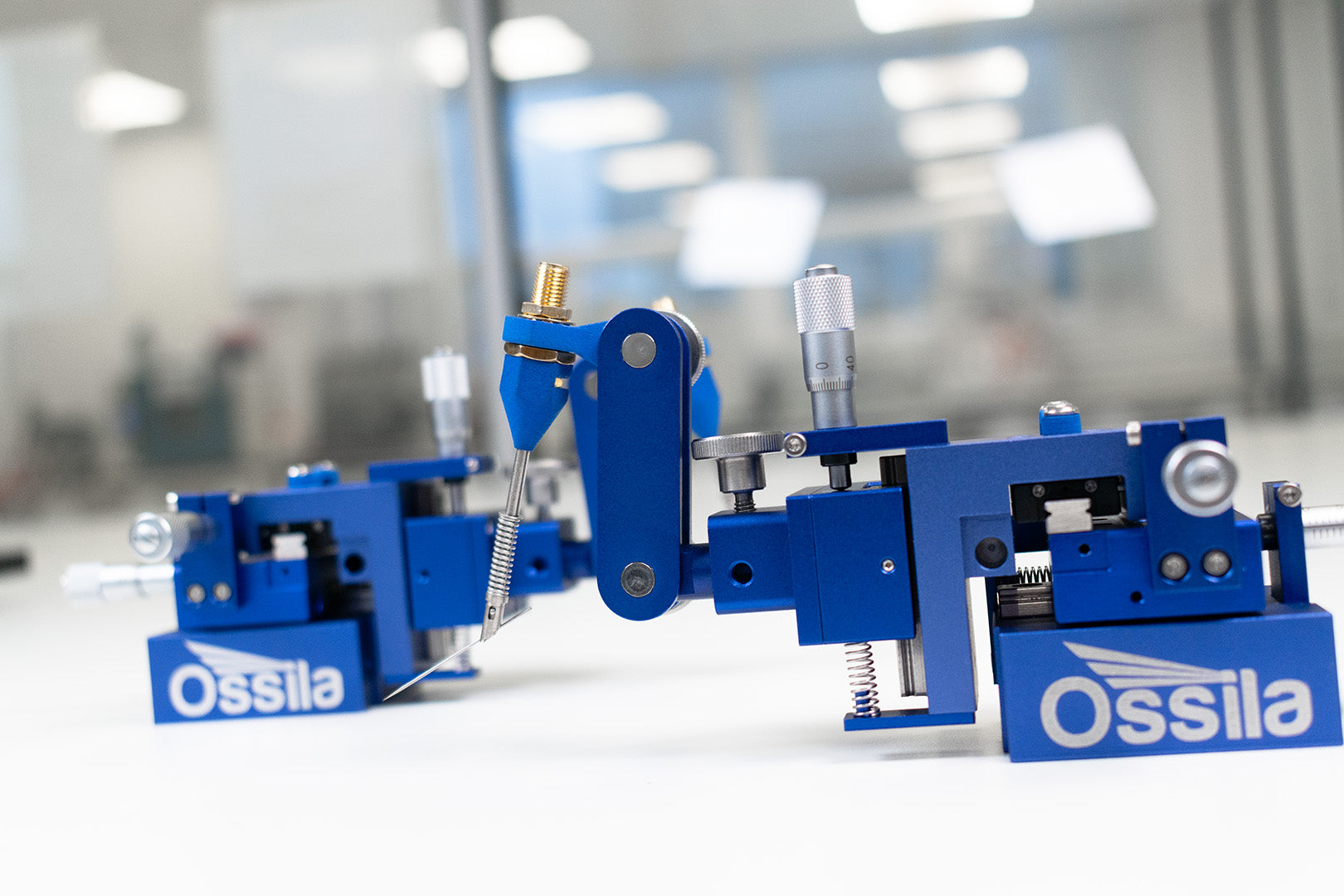
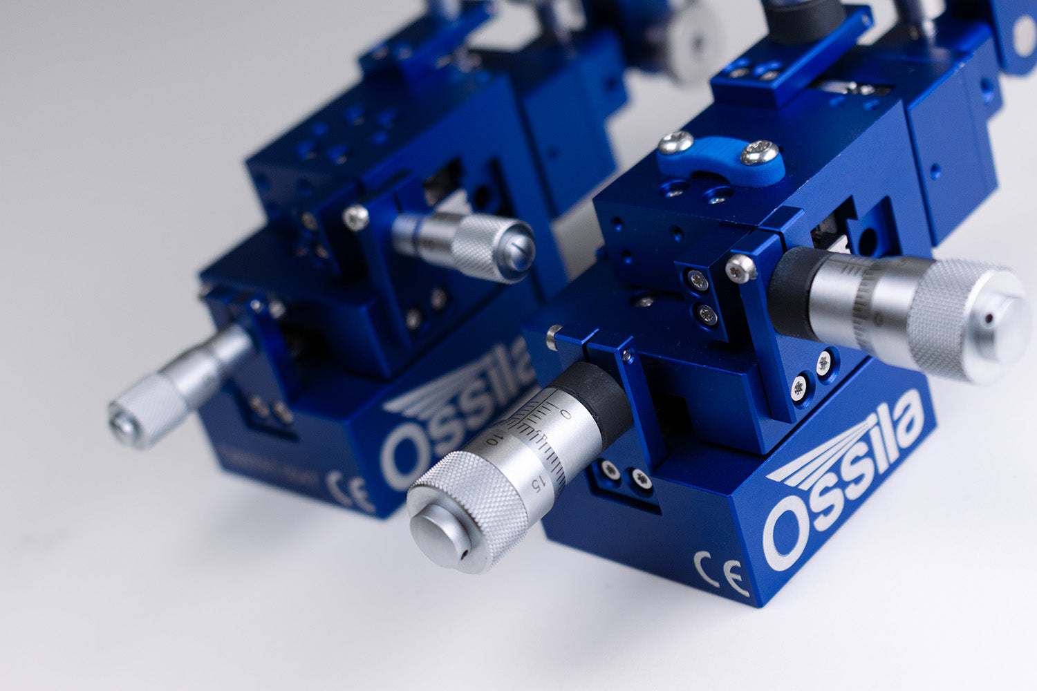
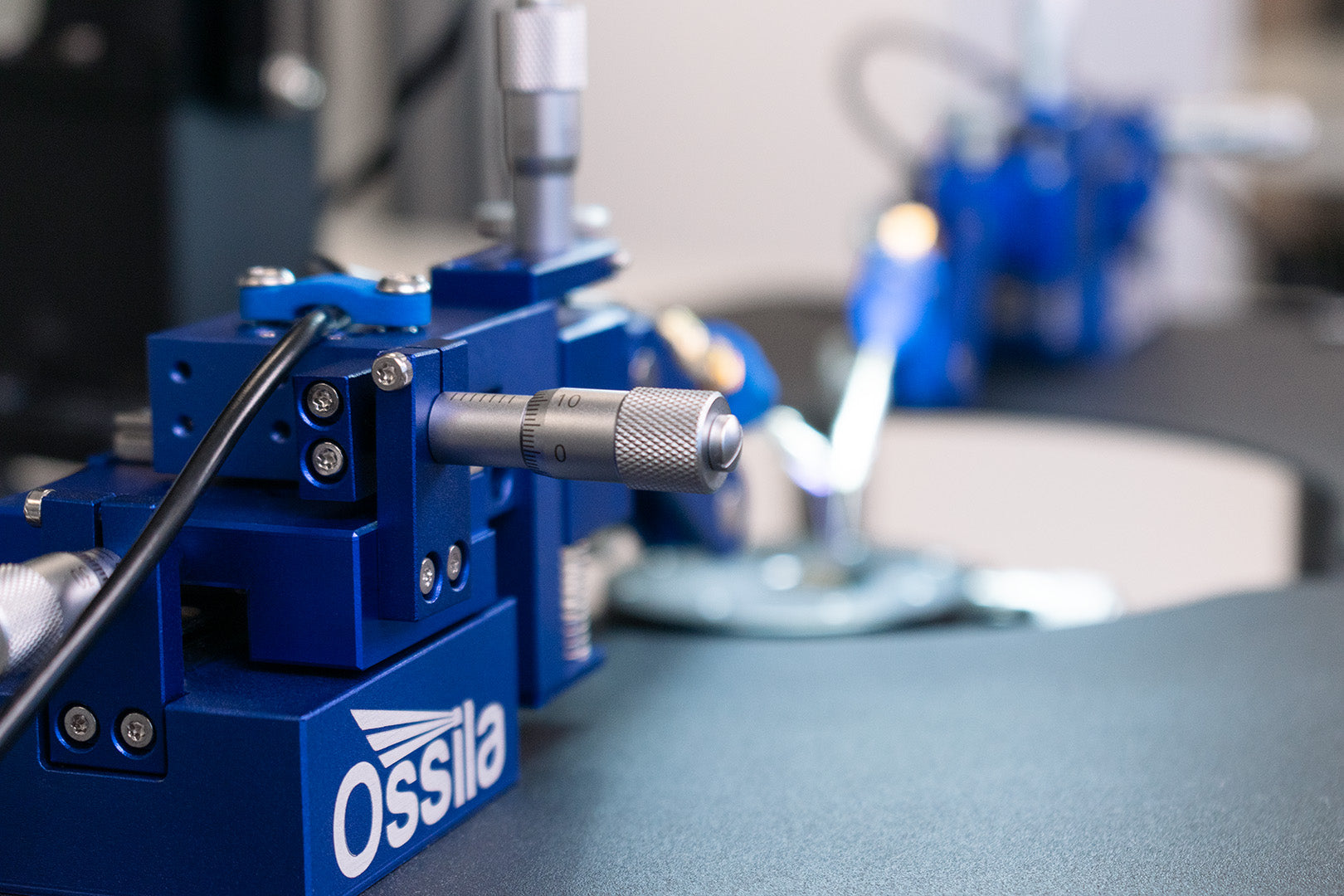
Select the correct handedness for your experiments, with a discount when you buy a pair. The probe is easy to position without looking away from your microscope as each micrometer is aligned with the corresponding axis. Motion along a 6.5 mm graduated travel distance plus the secure magnetic base and compact size make it possible to use multiple micromanipulators on benchtop probe stations without crowding your workspace.
The included SMA to SMA coaxial cable supports a range of adapters and can be used to connect the micromanipulator to nearly any source measure unit. For semiconductor devices, we recommend pairing our micromanipulators with the Ossila Probe Station and Source Measure Unit to complete your electrical characterization setup.
Micron-Level Resolution
Accurate motion with minimal backlash or drift and a 2-8 µm positioning resolution
Dual Setup Available
Ergonomic left and right-handed micromanipulators available, or save with a pair
Low Leakage Current
Less than 100 pA leakage current at ± 75 VDC, and less than 0.3 Ω path resistance
Fully Equipped
20 μm tungsten probe tip included as standard, or fit with a universal tool clamp
Choosing the Right Positioning Resolution
When it comes to precision, some micromanipulators offer finer control with higher resolution micrometers. The positioning resolution of your micromanipulator determines the smallest achievable motion of the probe. Choosing the right resolution depends on the scale and sensitivity of your experiment as improved resolution can be key in applications that demand extreme accuracy.
The Ossila Micromanipulator is available with either a 10 μm or 5 μm micrometer readout resolution. This refers to the markings on the micrometers. In practice, since the micrometers offer a continuous adjustment rather than a stepped adjustment, the smallest achievable motion is finer than the readout resolution.
The smallest achievable motion on the 10 μm resolution micromanipulators is 4-8 μm, while the larger micrometers on the 5 μm resolution micromanipulators allow you to move the probe by as little as 2-4 μm. Both resolutions offer repeatable positioning using precision linear bearings without backlash or drift but, if you need better resolution, upgrading to higher resolution micrometer heads is an affordable and effective solution.
How Does a Micromanipulator Work?
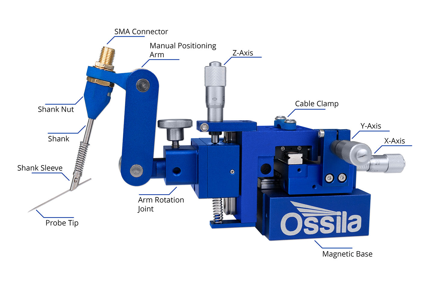
A typical micromanipulator includes several main components: a probe holder, adjustable probe arm, micrometer axis controls, and a magnetic base. Depending on your application, you can attach other tools such as pipettes, syringes, or optical fibers, via a universal tool adapter.
Manual micromanipulators are popular because they offer intuitive, hands-on control, straightforward operation, and affordability. When the micrometer controls align with the direction of movement, the probe moves as an extension of your hand, providing excellent tactile feedback for precise positioning.
For electrical experiments, an SMA connection lets you connect your micromanipulator to your test equipment (like the Ossila Source Measure Unit). A built-in cable clamp helps minimize electrical noise by securing your coaxial cables, ensuring cleaner data. Meanwhile, the magnetic base keeps your measurement environment stable when set up on metal platens, like when using the Ossila Probe Station.
Technical Specifications
Motion
| T2007A1 | T2007B1 | |
|---|---|---|
| Drive Axes | X, Y, Z | X, Y, Z |
| Drive Fine Movement | Micrometer | Fine-pitch micrometer |
| Maximum Axis Travel | 10 mm | 10 mm |
| Graduated Axis Travel | 6.5 mm | 6.5 mm |
| Micrometer Readout Resolution | 10 μm | 5 µm |
| Micrometer Head Thread Pitch | 50 threads per inch | 100 threads per inch |
| Smallest Achievable Motion | Approx. 4-8 µm | Approx. 2-4 µm |
| Maximum Probe Diameter | 0.8 mm | 0.8 mm |
Probe
| Probe Material | >99.95% pure tungsten |
|---|---|
| Probe Tip Diameter | 20 μm |
| Probe Leakage Current | <100 pA at ± 75 VDC |
| Probe Path Resistance | ≤0.3 Ω |
| Probe Length | 32 mm |
| Probe Shaft Diameter | 0.508 mm |
| Probe Connection | SMA |
Leakage Current and Probe Path Resistance
When using a micromanipulator for any electrical characterization, it is important to minimize resistance in the measurement chain wherever possible. In the case of a micromanipulator connected to a measurement device, this additional resistance can come from three sources: contact resistance, system resistance and lead resistance.
- Lead resistance refers to the resistance introduced by cables, wires or leads connecting the probe to the instrument.
- Contact resistance refers to the resistance at the interface between the probe tip and the material under test. This can be affected by incomplete connections, pad geometry, surface roughness, oxide layers or contamination.
- System resistance denotes any resistance encountered on the path from the probe tip through the manipulator arm. Oscillations or displacements of the manipulator arm, or poor contact seating can increase this path resistance.

In practice, the Ossila micromanipulator reports a path resistance of <0.3 Ω (tip-to-instrument). However, this value depends on the quality of contact between probe and substrate, and type of cable used.
Leakage current refers to any unintended current flow outside the desired circuit path — for example, through insulation, across surfaces, or via parasitic paths. In precision device characterization (i.e. on the scale of nanoamperes or picoamperes), even small leakage currents matter, contributing to noise or offset error. The Tungsten probes included with the Ossila Micromanipulator exhibits leakage current of <100 pA at 75 V DC.
Ossila Micromanipulator Features
Precise Three-Axis Positioning
Use the micropositioners to move your probe by as little as 2 μm along three-axes for precise and reliable probing. The precision linear bearings on each axis provide smooth and repeatable movement, while the spring-loaded bearings eliminate backlash so you can get accurate measurements in sensitive experiments.
Comfortable Manual Control
Stay focused on your microscope with blind probe control. For each direction of movement, the micrometer controls are aligned with the corresponding axis so you can intuitively make adjustments. With magnetic bases, our micromanipulators also pair seamlessly with the Ossila Probe Station to complete your probing setup.

DC Current Probing
Get accurate measurements in your sensitive electrical tests with a low leakage current and path resistance. Set up your micropositioners quickly using the SMA connector and prevent vibration or noise from disrupting your results with the secured coaxial cable. Connect to nearly any source measure unit using a suitable adapter.
Adapt to Your Experiments
Swap the tungsten probe for a wide range of probes, syringes, micropipettes, vacuum needles, optical fibers, and more. The Ossila Micromanipulator is designed for labs that demand versatility so you can take advantage of excellent positioning accuracy whatever your application or experimental requirements.
Micromanipulator Applications
Micromanipulators are used across a wide variety of smale-scale experiments. Some common examples include:
- Device Characterization: Micromanipulators position probes to measure a wide range of electrical properties. These measurements provide insights into the device's performance, reliability, and suitability for specific applications.
- Material Development: Micromanipulators are used them to explore the electrical properties of novel materials like organic semiconductors, 2D materials, and nanostructures.
- Wafer-Level Testing: In semiconductor manufacturing, before a wafer is diced into individual chips, micromanipulators are used to assess chip performance and identify defects early.
- Failure Analysis: When a device malfunctions, micromanipulators probe individual components and connections to trace faults.
- Optoelectronic Testing: When integrated with optical sources and detectors, micromanipulators can be used to test optoelectronic devices, such as photodiodes, LEDs, and laser diodes.
- Electrophysiology: Micromanipulators are used to position microelectrodes to record electrical activity from individual neurons or muscle cells. This allows researchers to study ion channel behavior, synaptic transmission, and neural circuitry in real-time.
- Cell Biology: From injecting biological molecules into cells to performing patch-clamp experiments or isolating specific cells for further analysis, micromanipulators have many uses in biology applications.
- Genetic Engineering: Micromanipulators are important in research that involves microinjecting DNA or RNA into cells, and in microdissection to manipulate or dissect small tissue samples under a microscope.
Product Gallery
Additional Specifications

| Base Type | Permanent Magnet |
|---|---|
| Body Material | Anodized Aluminum |
| Dimensions (L x W x H) | 155 mm x 74 mm x 78 mm (6.10" x 2.91" x 3.07") |
| Extended Dimensions (L x W x H) | 231 mm x 77 mm x 84 mm (9.09" x 3.03" x 3.31") |
| Weight | 400 g |
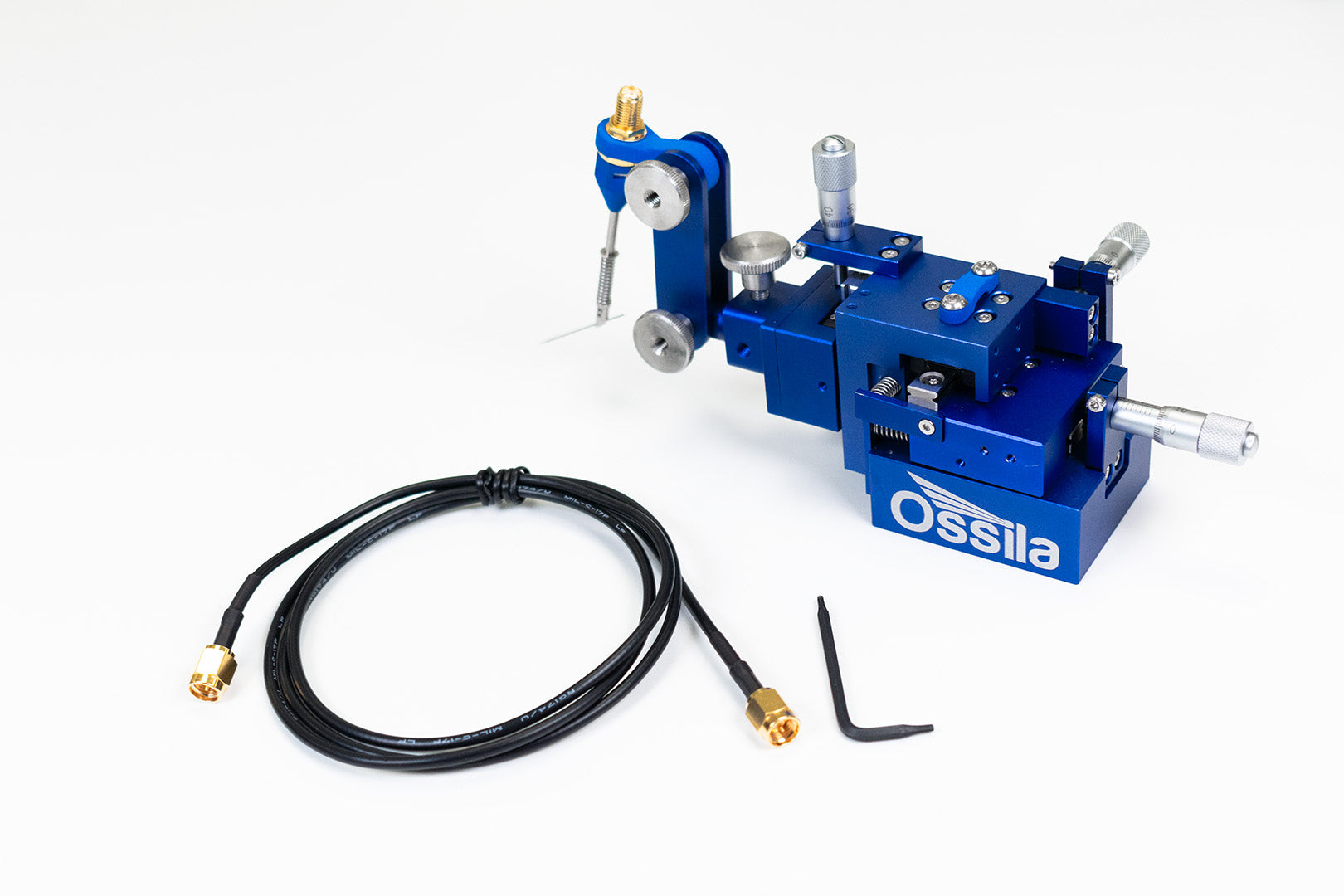
In the Box (Per Unit)
- Micromanipulator
- 20 μm tungsten probe tip
- 1 m SMA to SMA coaxial cable
- Documentation
Complete Your Electrical Characterization Setup


Connecting Micromanipulators to Measurement Instruments


The Ossila Micromanipulators can be paired with the differential interface, which accepts up to three SMA inputs and delivers dual-channel BNC outputs to connect straight into the SMU channels.
When a true four-wire configuration is required, the micromanipulator can be connected via the Ossila SMA to Banana Adapter (coming soon), which offers four SMA inputs and corresponding banana terminals (Force HI, Force LO, Sense HI, Sense LO). For simpler single-channel setups, it can also be used with the triaxial adapter, providing a straightforward SMA-to-triaxial connection.
Ossila micromanipulators are designed to connect to a wide range of common measurement instruments using an appropriate adapter. Compatible adapters include:
| Measurement Instrument | Compatible Adapter |
|---|---|
| Ossila Source Measure Unit | Differential Interface (SMA-to-BNC) |
|
Keithley 2400 series, Keysight B2900 series, Rhode & Schwarz NGU series |
Micromanipulator SMA to Banana Interface |
|
Keithley 2450 series, Keithley 2600B models (check model), Keysight B1500A series |
Triaxial adapter (SMA-to-triaxial) |
*Ossila is not affiliated with, endorsed by, or sponsored by Keithley, Keysight, Rhode & Schwarz, or any other instrument manufacturers mentioned. All product names and trademarks are the property of their respective owners and are used for identification purposes only. Compatibility information is based on published interface standards and has not been confirmed through Ossila testing.
Using The Ossila Micromanipulator
 Getting the Most Out of Your Ossila Micromanipulator
This guide will help you set up, connect, and tailor your Ossila Micromanipulator to your specific research needs.
Read more... Connecting the Micromanipulator to the SMU
Learn how to use your micromanipulator with the Ossila Source Measure Unit. Plus, pick up some general tips and tricks for getting the most out of sensitive electrical probing measurements.
Read more...