
Electrical Characterization System
Complete Electrical Characterization Platform at a Fair Price
Reliable device testing with a professional probe station and flexible source measure unit
Overview | Specifications | Features | Gallery | In the Box | Related Products | Resources and Support
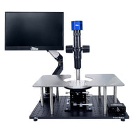
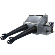
Comprehensive characterization in small-scale electronics experiments, this system includes everything you start your testing your samples. Combine a stable, manual probing platform, complete with integrated vibrational dampening, electrical isolation, 60 fps USB camera, and lag-free display, with a dual channel source measure unit.
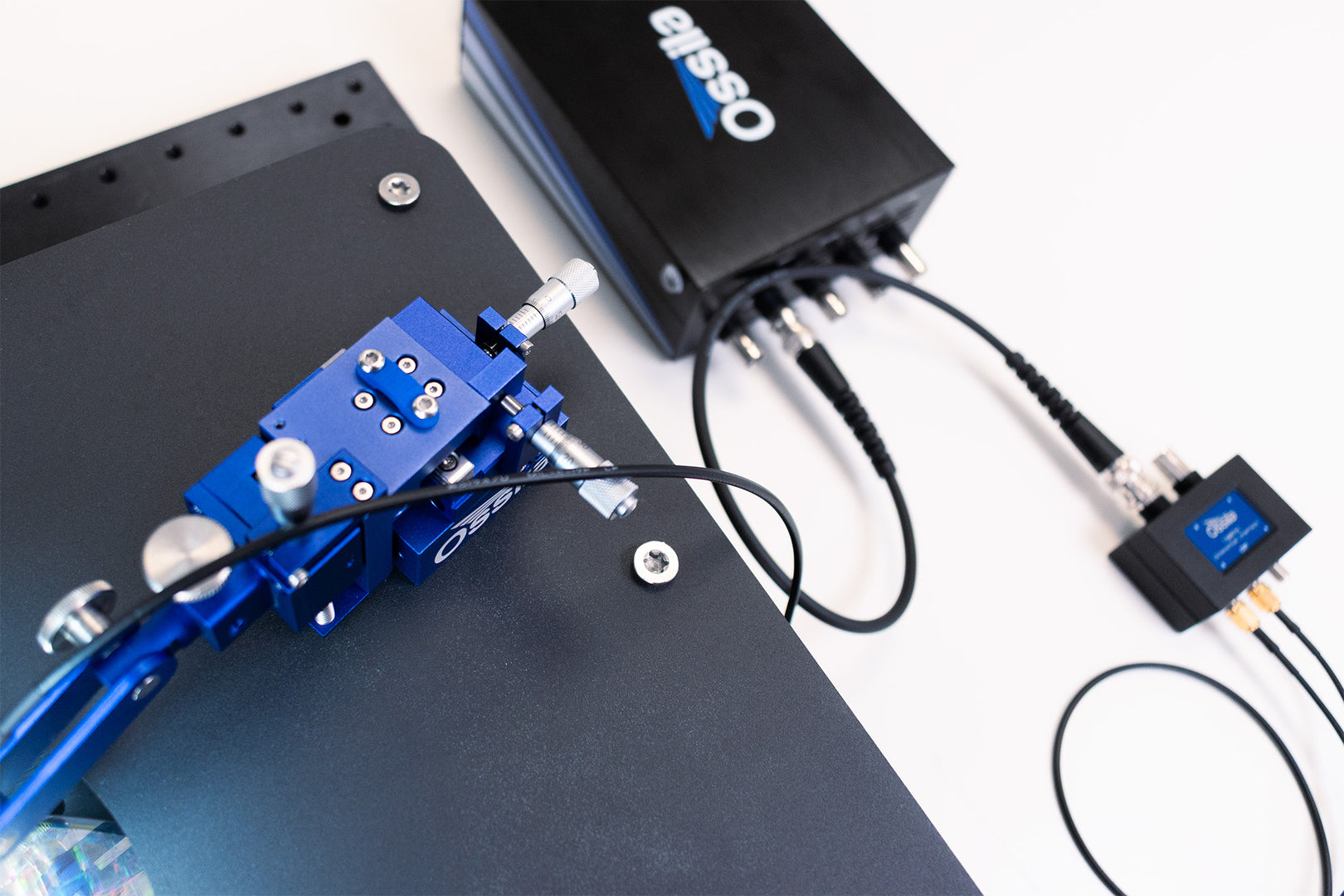
Easily connect your micromanipulators to the source measure unit and measure the I-V characteristics of many devices including photovoltaics, LEDs and OLEDs, transistors, and more. The dual channel SMU contains four instruments on one board: two SMUs (voltage source, current sense) and two precision voltage sense channels - plus a general-purpose shutter/trigger channel for integration with other instruments. The included diaphragm vacuum pump has minimal noise, no maintenance and integrated pressure gauge for simple and reliable sample positioning.
Complete, Professional System
For reliable electrical characterization
Dual Channel
Source Measure Unit
With free software for fast measurements
Flexible
and Adaptable
Optical breadboard base and spacious magnetic platens
Prioritize
Ergonomics
Intelligent design for
a simple workflow
Specifications
| Footprint | (L x W x H) 50 x 35 x 60 cm |
|---|
Base Station & Platens
| Base | Aluminum optical breadboard, 25 mm hole spacing |
|---|---|
| Vibration Isolation | Elastomeric vibration dampening mounts |
| Natural Frequency | 12 Hz |
| Effective Vibration Isolation | >17 Hz |
| Maximum Supported Load | 880 N total |
| Platen Material | Ferromagnetic stainless steel |
| Platen Height | 150 mm |
| Platen Capacity | Up to 8 Ossila Micromanipulators |
| Overall Dimensions | (L x W x H) 50 x 35 x 19 cm |
Chuck Stage
| Stage Travel | 25 mm (X, Y), 10 mm (Z), 360° (coarse rotation), 15° (fine rotation) |
|---|---|
| Stage Resolution | 0.01 mm (X, Y, Z), 0.1° (rotation) |
| Minimum Substrate Size | 5 mm diameter |
| Maximum Substrate Size | 150 mm diameter |
| Chuck Diameter | 155 mm |
| Chuck Material | Aluminum |
| Chuck Type | Vacuum (selectable zones) |
| Chuck Isolation | >99 MΩ at 500 VDC |
| Chuck Leakage Current | <75 pA at ± 75 VDC |
| Vacuum Connection | Ø=6mm Push-In Tube, Female port |
Diaphragm Vacuum Pump
| Pump Type | Diaphragm (oil-free) |
|---|---|
| Maximum Flow | 7 L/min |
| Max. Vacuum (gauge) | -680 mbar (-510 mmHg) |
| Max. Vacuum (abs) | 330 mbar |
| Noise | <45 dBA at 1 m |
| Vibration | Low (dual-stage damped) |
| Motor Type | DC Brushless |
| Max. Power | 4 W |
| Rated Pump Lifetime | 6000 hours |
| Ventilation | External exhaust (Clean gas only, no liquids/gases that need to be recovered) |
| Suitable Media | Air and Non-Flammable, Non-Corrosive Dry Gases Only (e.g. Nitrogen, Argon) |
| Pump Head Material | PPS |
| Diaphragm Material | EPDM |
| Valve Material | EPDM |
| Gauge Units | mBar & mmHg |
| Tubing Connector | 6 mm Push-fit |
| Power Requirement | 24 VDC |
| Weight | 1 kg |
| Dimensions (L x W x H) | 15 x 12 x 14 cm |
Microscope
| Microscope Type | Monocular Zoom Lens (0.6x – 5.0x optical zoom) |
|---|---|
| Field of View | 9.3 mm – 1.1 mm |
| Working Distance | 86 mm |
| Camera Sensor | Sony IMX415 (4K, 1/2.8") |
| Maximum Resolution | 4.4 µm line spacing (228 lp/mm) |
| Live Output | USB 3.0 & HDMI (up to 60 fps at full resolution) |
| Camera Software Compatibility | UVC-compliant for plug-and-play viewing with Ossila software and most 3rd party software |
| Monitor | 15.6" 1080p, on a positionable arm |
| Total Magnification | 37x – 309x |
| Illumination | Adjustable LED (coaxial configuration) |
Micromanipulators
Motion
| 10 μm resolution | 5 μm resolution | |
|---|---|---|
| Drive Axes | X, Y, Z | X, Y, Z |
| Drive Fine Movement | Micrometer | Fine-pitch micrometer |
| Maximum Axis Travel | 10 mm | 10 mm |
| Graduated Axis Travel | 6.5 mm | 6.5 mm |
| Micrometer Readout Resolution | 10 μm | 5 µm |
| Micrometer Head Thread Pitch | 50 threads per inch | 100 threads per inch |
| Smallest Achievable Motion | Approx. 4-8 µm | Approx. 2-4 µm |
| Maximum Probe Diameter | 0.8 mm | 0.8 mm |
Probe
| Probe Type | Tungsten, 20 μm tip diameter |
|---|---|
| Probe Connection | SMA |
| Probe Leakage Current | <100 pA at ± 75 VDC |
| Probe Path Resistance | ≤0.3 Ω |
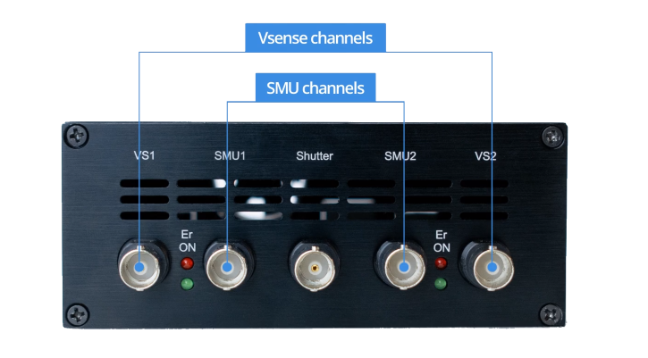
Source Measure Unit
Source Measure Units (SMU 1 & SMU 2)
The SMUs output a voltage and then measure both the voltage and current. The output voltage is always measured on the output to the BNC, rather than assuming it is at the set voltage. This is to account for any load effects, for example, short circuiting the output, or low impedance causing a small drop in voltage. Each source measure unit has multiple current ranges, so that you can measure both large and small currents with accuracy.
Voltage Source Specifications
| Range | Accuracy | Precision | Resolution |
|---|---|---|---|
| ±10 V | 10 mV | 333 µV | 170 µV |
Voltage Measure Specifications
| Range | Accuracy | Precision | Resolution |
|---|---|---|---|
| ±10V | 10 mV | 50 µV | 10 µV |
Current Measure Specifications
| Range | Max Current | Accuracy1 | Precision2 | Resolution | Burden |
|---|---|---|---|---|---|
| 1 | ±200 mA | ±500 µA | 10 µA | 1 µA | <20 mV |
| 2 | ±20 mA | ±10 µA | 1 µA | 100 nA | <20 mV |
| 3 | ±2 mA | ±1 µA | 100 nA | 10 nA | <20 mV |
| 4 | ±200 µA | ±100 nA | 10 nA | 1 nA | <20 mV |
| 5 | ±20 µA | ±10 nA | 1 nA | 0.1nA | <20 mV |
1Accuracy has been measured at the maximum current of the range.
2Precision has been measured at the highest OSR (9).
Precision Voltage Meter Specifications (Vsense 1 and Vsense 2)
The voltage meters are designed to accurately sense small voltages while also having a wide dynamic range (±10 V).
| Range | Accuracy | Precision | Resolution |
|---|---|---|---|
| ±10 V | 10 mV | 50 µV | 10 µV |
Shutter/Trigger
The Shutter/Trigger can be used either as an input or an output. It can be used to send a trigger signal to other instruments or configured to wait for a trigger from other instruments. The voltage level of this BNC is 5 V because any higher may cause damage to the port.
Find out more about the Ossila Source Measure Unit
Electrical Characterization System Features
Confidence in Your Measurements
Achieve consistent, high-quality data in a low-noise, stable measurement environment. The precision-engineered chuck, vibration isolation, low noise vacuum pump and electrical grounding directly support the reliability and repeatability your research depends on.

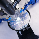
Precise Probing
With a low leakage current and path resistance, the micromanipulator is designed to perform in DC semiconductor measurements. Adjust your micromanipulator probe to a resolution as low as 4 μm and experience smooth, repeatable movement along the precision linear bearings on each axis.

Five Independent Channels
Features dual source measure and voltmeter channels. Two SMU channels output voltage while measuring current and/or voltage, and two separate voltage measurement channels measure voltage sourced by external components. The shutter/trigger channel allows external control and programming.
Wide Voltage and Current Range
Choose between five separate current ranges to suit your experimental needs. Plus, 10 different speed/resolution settings. Take measurements at DC or low frequency over a voltage range from -10 V to +10 V, with a current flow from 10 nano-amps (nA) to 200 milliamps (mA).
Practical and Intelligent Design
Focus on your research and eliminate awkward movements, even during long experiments. Essential stage controls and a swing-away microscope mount provide unobstructed access to the stage for easy setup, precise probing, and fast sample changes. The 60 fps camera allows easy positioning with minimal lag.
Electrical Characterization System Gallery


In the Box
- Probe station with microscope, camera, and display
- 4 x Micromanipulators (2 left-handed, 2 right-handed)
- Source measure unit
- Diaphragm vacuum pump
- 2 x Differential Interfaces
- Probe tip set (10 x 20 μm tungsten probe tips)
- 4 x SMA to SMA coaxial cables (1 meter)
- 4 x BNC to BNC cables (50 ohm, 1 meter)
Related Products


More From Ossila


Resources
 What Features Do You Need in a Probe Station?
Probe stations are incredibly useful for a wide range of experiments from semiconductor characterization to electrophysiology experiments. However, each experiment will have different requirements and every lab has its own demands. The question stands: what is the right probe station set up for you?
Read more...