Getting the Most Out of Your Ossila Micromanipulator
This guide is designed to help you set up, connect, and tailor your Ossila Micromanipulator to your specific research needs. We believe that precision instruments should provide intuitive control, and our goal is to help you achieve that. Whether you are performing an initial setup or advanced modifications, we are here to support you.
Initial Setup: Positioning and Probe Tip Installation
Your Ossila Micromanipulator is delivered fully assembled and configured for either left- or right-handed use. The initial setup is straightforward.
- Positioning the Base: Begin by placing the micromanipulator on your platen. The powerful magnetic base is designed to hold it firmly in place while still allowing for deliberate adjustments to its position.
- Familiarize Yourself with the Controls: Take a moment to test the full range of motion. Evaluate the coarse adjustment of the arm and the fine control of the three micrometers.
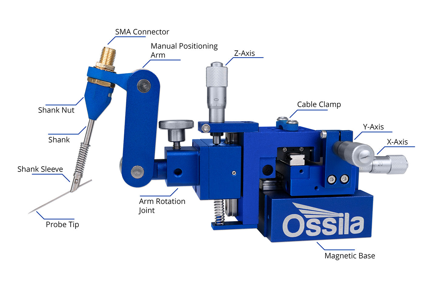
- Cable Management: Attach the SMA cable to the probe holder. Use the plastic clip on the Y-axis carriage to secure the cable, leaving sufficient slack to allow for free movement along the Z-axis until you are satisfied with the final position.
- Installing a Probe Tip: To install a probe tip, pull back the spring-loaded sleeve at the end of the holder. This reveals a 0.8mm diameter hole angled at 45°. We recommend inserting the blunt end of the probe first to protect the fragile, sharp tip from accidental damage.
A Note on Travel Range: The micrometers have a 10mm travel range for fine adjustments. To achieve the best results and avoid damaging the mechanism, position the probe tip as close as possible to your target using the coarse arm adjustment first. This reserves the full 10mm of travel for your most precise movements. Reaching the end of a micrometer's travel indicates that you should retract the probe and reposition the arm or base.
Connecting to Your Measurement Equipment
A correct connection scheme is essential for acquiring clean, accurate data. The optimal configuration depends on your specific experiment, but the following principles and solutions can guide you.
Key Considerations for Accurate Measurements
- Shielding vs. Guarding: These terms are often confused but are critically different.
- Shielding is your primary defense against environmental electrical noise (EMI/RFI). This is typically achieved by placing your entire setup inside a grounded metal enclosure (a Faraday cage or probe station). The coaxial cable's outer conductor also acts as a shield for the signal wire along its length.
- Guarding is an advanced technique used in ultra-sensitive, low-current measurements to minimize leakage currents. In a triaxial cable, a guard conductor runs alongside the signal wire and is kept at the same potential. This prevents current from "leaking" from the signal wire into the surrounding insulation.

- Leakage Currents: For low-current work, ensure all components are clean and possess high insulation resistance. Be mindful of environmental factors like humidity or vibration that can introduce noise.
- Cable and Probe Management: Keep cables as short as is practical and anchor them to your optical table or probe station to minimize stray capacitance and measurement errors arising from movement.
Connection Solutions
We offer several tools to simplify connecting our micromanipulators to your equipment.
- For Ossila SMUs: Our Differential Interface is designed for connecting up to three micromanipulators to two SMU channels. It is ideal for applications requiring two single-conductor signals to be measured differentially, such as characterizing multi-terminal devices. It consolidates your signals into standard BNC connectors that interface directly with our Source Measure Unit or other coaxial-connectorized equipment.

- For Banana Plugs: If your instrument uses banana plugs, the Differential Interface can serve as an effective adapter from SMA to BNC. Widely available BNC-to-banana adapters can then be used to complete the connection.
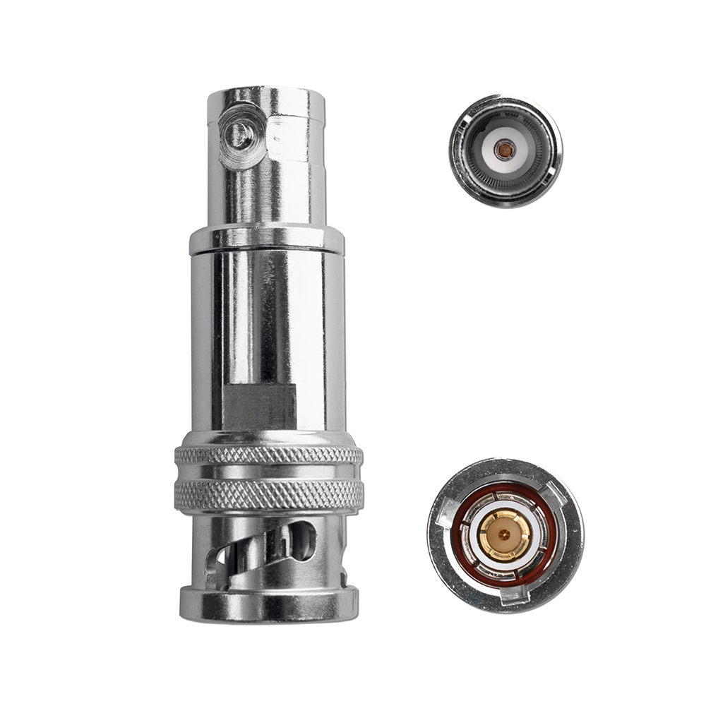
- For Triaxial Connections: High-end electrometers often use triaxial connectors (comprising a center conductor, an inner "guard" shield, and an outer "ground" shield). Connecting our standard coaxial cable requires a specific adapter. The choice is critical and depends on your measurement needs.
- Type 1 (Coax Shield -> Triax Guard): This adapter connects the coaxial cable's shield to the instrument's guard terminal, allowing the coax cable to be used for guarding. This configuration is suitable when your primary goal is to extend the guarding from the instrument through the cable to minimize leakage currents. Crucial Safety Warning: In this configuration, the outer metal shell of the coaxial cable and its connectors will be at the guard potential, which may be high. It is no longer a ground shield and could pose a shock or short hazard.

- Type 2 (Coax Shield -> Triax Outer Shield): This is an effective general-purpose solution. It connects the coaxial shield to the instrument's ground, using it purely for EMI shielding. The triaxial guard pin is left unconnected. This is suitable for most measurements where guarding isn't strictly necessary but robust shielding is desired.

- Type 3 (Coax Shield -> Triax Guard & Outer Shield): This type shorts the instrument's guard and ground terminals together. This defeats the purpose of guarding and should generally be avoided for sensitive DC measurements but is useful for some general-purpose applications.

We offer a range of adapters to help you connect to your specific instruments. If you are uncertain about your requirements, please ask. We are happy to help you determine the best solution for your setup.
Modifying Your Micromanipulator
We designed our micromanipulator to be adapted to your evolving research needs.
Changing the Probe/Tool Holder
Every application is different, and every micromanipulator doesn’t always need to support a tungsten probe tip. For applications where you would like to manipulate fiber optics, micro-pipettes, third-party probe tip holders, or any other equipment, you can replace the included probe tip holder with the Ossila Universal Tool Clamp. This modification expands the functionality of your micromanipulator and requires no tools, being an effortless process. When reassembling the arm, ensure the correct order, specifically making sure there are compression washers between each arm and each device. This can be done with the provided thumb screws.
Maintaining Your Micromanipulator’s Performance
To ensure the longevity and continued precision of your manual micromanipulator, regular care and proper handling are essential. These simple steps will help you get the most out of your instrument over its lifetime:
- Keep it Clean: Dust, debris, and oil can impair the smooth movement of the micrometers and linear rails. Regularly inspect and gently clean the exposed mechanisms with a soft, lint-free cloth. Avoid using harsh chemicals or abrasive materials.
- Handle with Care: Your micromanipulator is a precision instrument. Avoid sudden impacts or forceful movements. When adjusting, use gentle and deliberate actions.
- Proper Storage: When not in use for extended periods, store the micromanipulator in a clean, dust-free environment. Consider covering it to prevent dust accumulation.
Here to Help
Your success is our priority. We build tools to accelerate your research, and our support extends beyond physical hardware. This guide is a starting point, but our assistance does not end here.
Remember, we want you to succeed. If you are unsure about any step, or if something has gone wrong, please email us at support@ossila.com. We encourage you to contact us for assistance to prevent a minor issue from escalating. Any modification not explicitly described in an official Ossila guide may void your warranty, so it is always best to check with us first.
If you have questions, encounter a challenge, or wish to discuss the best approach for your experiment, please get in touch. We are here to help you get the most out of your Ossila Micromanipulator and achieve your research goals.
Contributors
Written by
Product Developer
Diagrams by
Graphic Designer