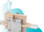
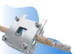
Advanced GDE Flow Cell
Compact Advanced Flow Cell with High Current Density
Reduce the ionic path length and lower ohmic resistance with a narrower channel
Specifications | In the Box | Gallery | Literature | Related Products | Technical Support
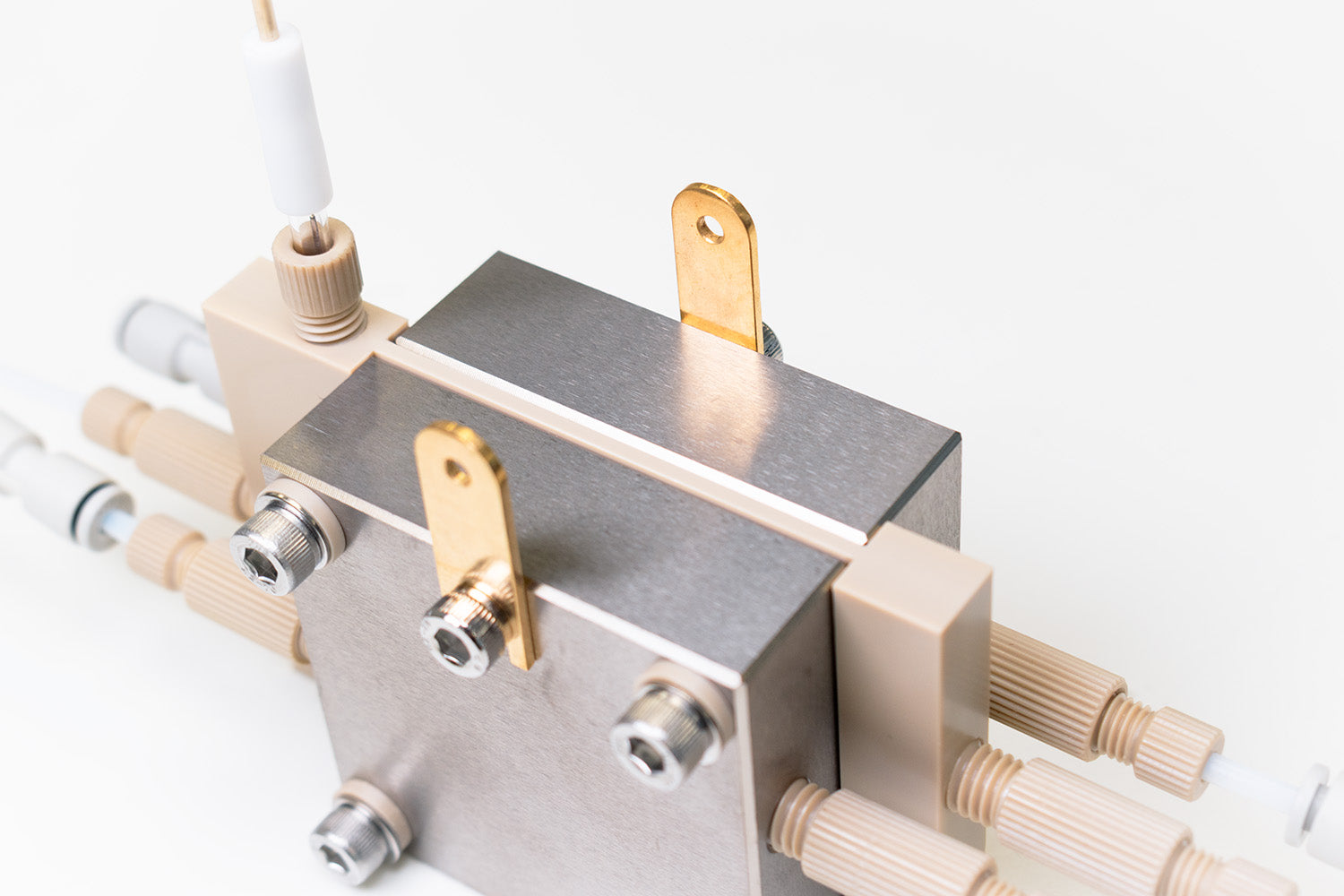
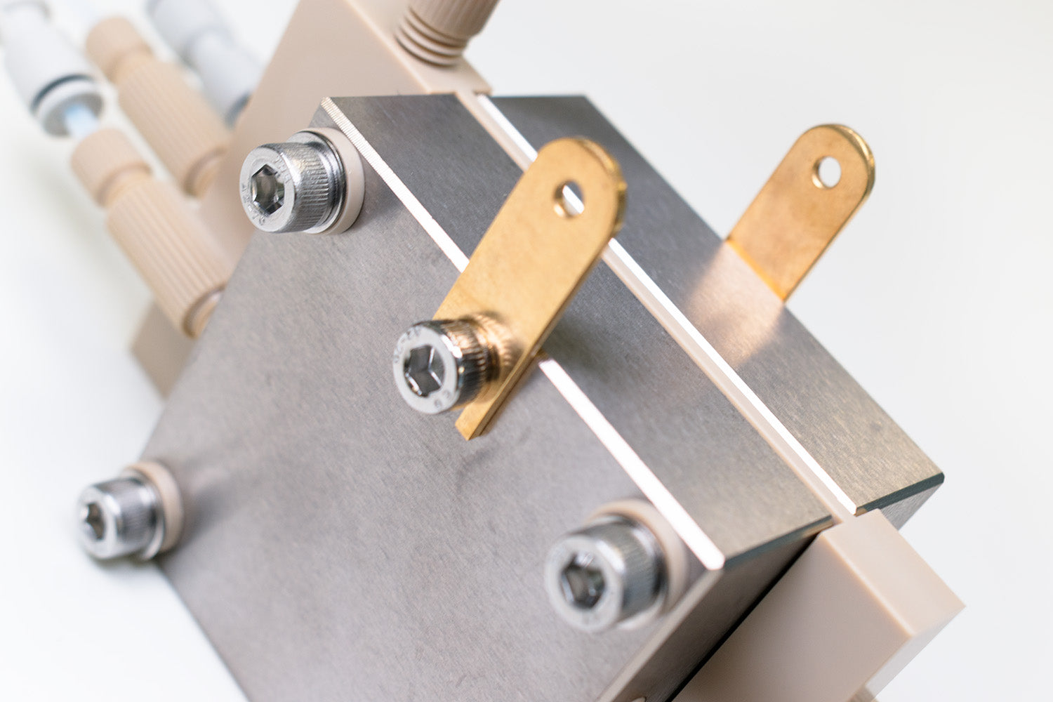
A highly specialized electrochemical device that creates a dynamic three-phase boundary, where gas reactant, liquid electrolyte, and solid catalyst meet and react at the interface of a porous, gas-permeable working electrode. GDE cells overcome the limitations of gas solubility in liquid electrolytes by feeding gaseous reactants directly to the catalyst surface, substantially increasing reaction efficiency and achievable current density.
The advanced cell has a narrower membrane channel between the cathode and anode chambers compared to our standard cell. This reduces the ionic path length through the catholyte, lowering ohmic resistance and supporting operational current densities above 200–400 mA/cm2.A continuously circulating liquid electrolyte chamber removes reaction products in real time and suppresses competing hydrogen evolution.
The advanced GDE flow cell can be used for a wide range of standard experiments, including CO2RR, NRR and ORR. Additionally, it is particularly useful if you are scaling your experiments towards industrially relevant current densities.

Aqueous Flow Cells
Continuous liquid products removal

Industrial Current Densities
Operational current densities above 200-400 mA/cm2

Three-phase Boundary Design
Preventing mass-transport limitations

Expert Support
From in-house scientists & our
customer care team
Specifications
| Cathode and Anode Field Plate/ Chamber Material | Titanium, TA2 (with serpent flow fields) |
|---|---|
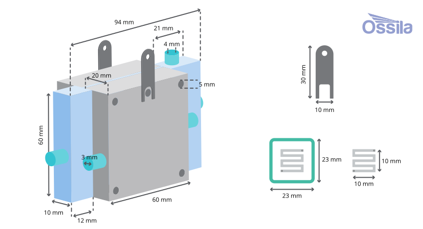
| Cathode and Anode Field Plate/ Chamber Dimensions | 60 mm x 60 mm x 19 mm (H x W x T) |
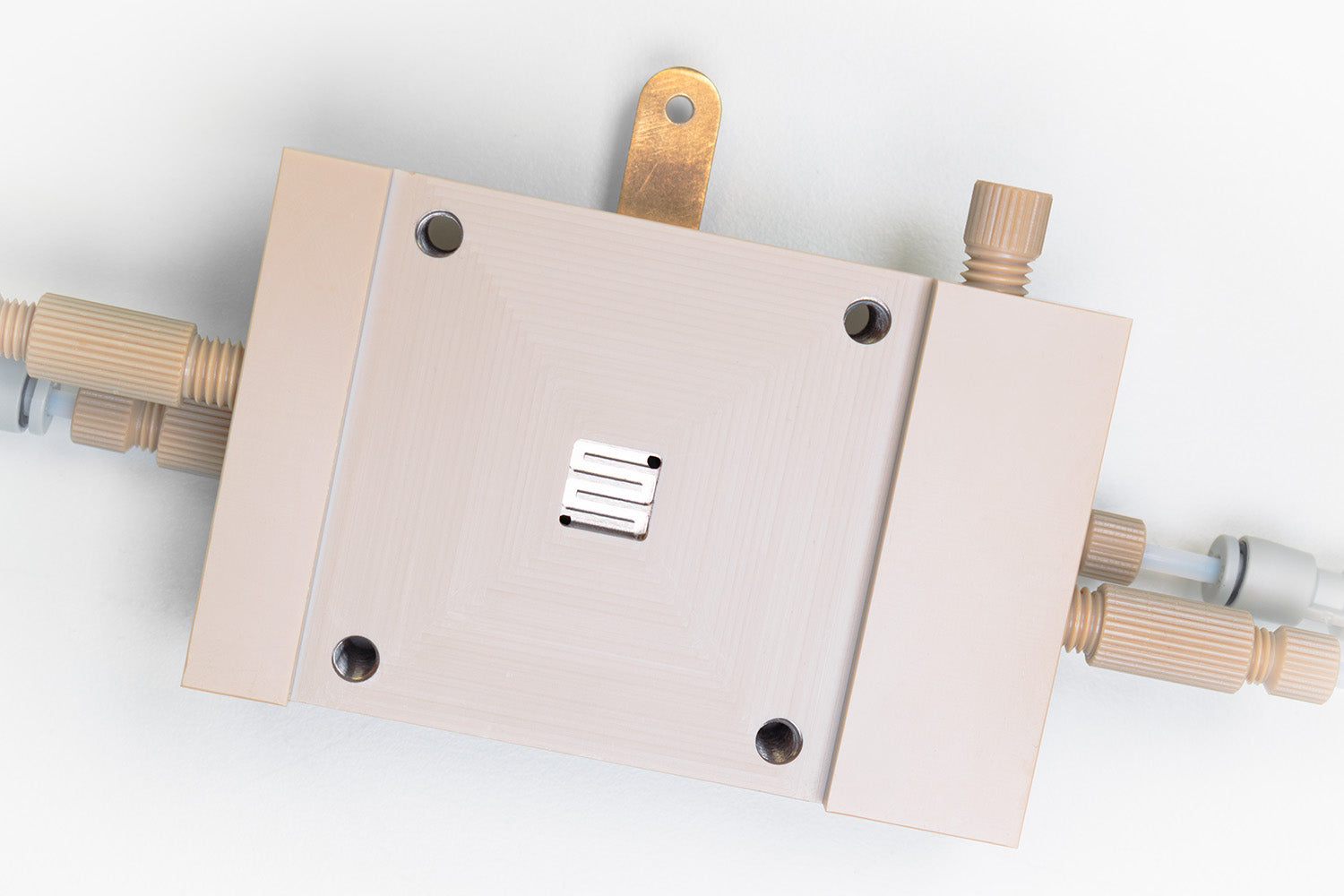
| GDE Working Area | S-shaped, 1 cm x 1 cm, 1.5 mm width and depth |
| Catholyte Chamber Material | PEEK (1 cm x 1 cm window, 2 mm depth) |
| Spacing Between Cathode and Anode Chambers | < 2.5 mm |
| Reference Electrode | Ag/AgCl (⌀ 4mm) |
| Gaskets | FKM and PTFE (52 mm x 52 mm, see thickness and window sizes below) |
| FKM Gasket Thickness (15 mm x 15 mm window) | 0.2 mm, 0.3 mm, 0.8 mm, 1.0 mm |
| FKM Gasket Thickness (10 mm x 10 mm window) | 0.2 mm |
| PTFE Gasket Thickness (15 mm x 15 mm window) | 0.2 mm, 0.25 mm |
Note: The flow cell can also be used as a zero-gap MEA electrolyzer once the flow field is removed.
What is a Gas Diffusion Electrode?
The GDE itself is built from three functional layers that together support a stable solid-liquid-gas three-phase boundary:
- The porous gas diffusion layer, typically carbon paper, carbon cloth, or metal mesh, acts as the mechanical and electrical backbone of the electrode and lets reactant gas through while keeping liquid electrolyte out.
- A thin microporous layer, typically made from carbon black nanoparticles mixed with a hydrophobic polymer such as PTFE, prevents the liquid electrolyte from flooding the gas pores.
- The catalyst layer, a dispersed layer of catalyst nanoparticles with an ionomer or binder microporous layer.
Our Standard GDE flow cell can accommodate many suitable GDEs, with a working area of 1 cm x 1 cm.
In the Box*
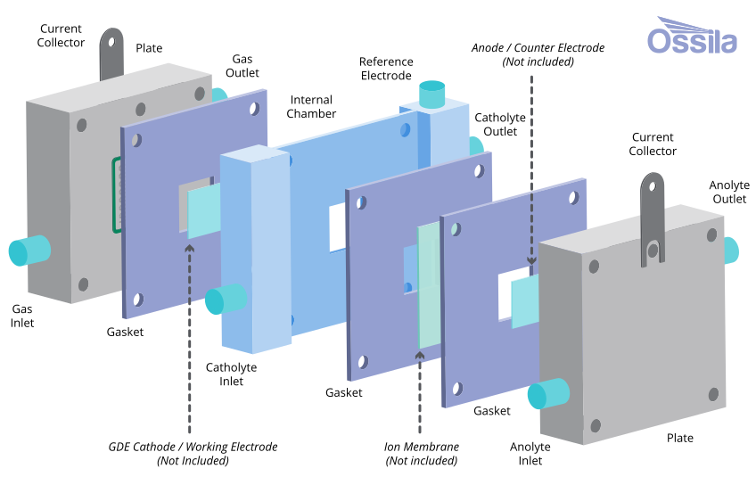
- Titanium cathode/anode chambers
- PEEK chamber
- Gaskets (PTFE & FKM)
- PTFE tube
- Tube cutter
- Contact collector leads
- Copper tape
- PTFE Gas & electrode stoppers
- Gas & electrode secure screws
- Assorted O-rings
- Screws & washers
- Gas locks
- PTFE tape
- Ag/AgCl (⌀4 mm) reference electrode
*GDE and membranes are not included in the original package and need to be purchased separately.
Product Gallery

Literature
- Y. Wu et al. (2024), Insights into electrolyte flooding in flexible gas diffusion electrodes for CO2 electrolysis: from mechanisms to effective mitigation strategies, J. Mater. Chem. A, 12, 14206-14228; DOI: 10.1039/D4TA01994F.
- T. Silva et al. (2025), Boosting New Electrochemical Reactor Designs to Improve the Performance in H2O2 Production Using Gas Diffusion Electrodes, ACS Sustainable Chem. Eng., 13 (8), 3172–3182; DOI: 10.1021/acssuschemeng.4c08826.
- G. Chen et al. (2025), Engineering Flow-Through Hollow Fiber Gas-Diffusion Electrodes for Unlocking High-Rate Gas-Phase Electrochemical Conversion, Adv. Mater., 37 (28), 2420391; DOI: 10.1002/adma.202420391..
Related Products