Non-woven, conductive, and permeable GDL substrate or PTL
Available with or without PTFE wet-proofing treatment
Specifications | Gallery | Pricing and Options | Related Products | Untreated vs Wet-Proofed | Technical Support
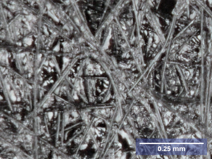
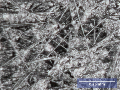
Our conductive carbon paper is a non-woven, porous sheet material made from carbonized fibres that is both highly conductive and permeable.
Its open, fibrous microstructure allows gas and liquid to pass through while maintaining electrical conductivity across the sheet, making it an ideal choice wherever a reaction needs efficient mass transport to and from a catalyst layer. This is particularly useful when using it as a gas diffusion substrate/ porous transport layer and electrode support across many electrochemical systems.
Conductive Carbon Paper Applications
- Fuel cells and water electrolyzers
- Batteries and supercapacitors
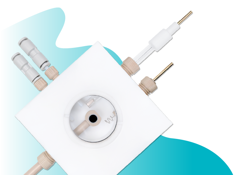
- Gas diffusion electrode (GDE flow cells)
- Standard Three-electrode Setups
- CO2 reduction reactors
- Sensors
Our carbon paper delivers exceptional in-plane conductivity and structural integrity thanks to its fibre web formation, thermoset resin impregnation, and high-temperature carbonization (1000–1500°C).
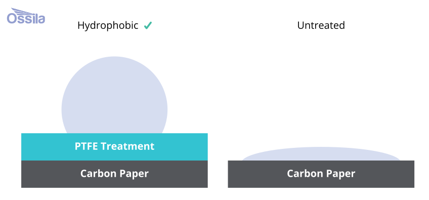
Ossila Carbon Paper is available to purchase with or without wet-proofing treatment depending on your requirements. A higher percentage of PTFE coating provide extra hydrophobicity at the expense of reduced conductivity, ideal for preventing flooding of the porous structure during operation. The uncoated carbon paper comes without a microporous layer (MPL) for applications where you need to apply your own catalyst layer, coating, surface treatment, or for use purely as a conductive or mechanical backing layer.
Key characteristics such as porosity, compressibility, and handling behaviour can vary noticeably between suppliers and grades, so these are worth checking closely when selecting a carbon paper for a specific cell design or assembly process.

Highly Porous
70–80% void volume, allowing gas and liquid transport through

Electrically Conductive
High conductivity = Efficient Current Collector

Hydrophobic (PTFE-treated only)
Prevents flooding of the porous structure during operation

Thermal and Chemical Stability
Stable across a range operating temperatures and pH levels
Specifications
Ossila Carbon Paper
| Product Code | C2061H10 | C2061H20 | C2061H30 | C2061P20 | C2061P30 |
|---|---|---|---|---|---|
| Thickness | 0.1 ± 0.01 mm | 0.2 ± 0.01 mm | 0.3 ± 0.01 mm | 0.19 ± 0.01 mm | 0.30 ± 0.01 mm |
| Wet Proofing | No | No | No | Yes (10%) | Yes (10%) |
| Dimensions | 21 cm × 20 cm | 21 cm × 20 cm | 21 cm × 20 cm | 21 cm × 20 cm | 21 cm × 20 cm |
| Porosity | 80% | 80% | 80% | 75% | 75% |
| Gas Permeability | < 11 mmH2O | < 11 mmH2O | < 11 mmH2O | < 12 mmH2O | < 12 mmH2O |
| Resistance (in-plane) | ≤ 10 mΩ·cm-2 | ≤ 11 mΩ·cm-2 | ≤ 12 mΩ·cm-2 | ≤ 16 mΩ·cm-2 | ≤ 18 mΩ·cm-2 |
| Flexural Strength | > 10 cm | > 10 cm | > 10 cm | > 10 cm | > 10 cm |
Conductive Carbon Paper Gallery
Pricing and Options
Ossila Carbon Paper Pricing
| Product Code | Thickness | Wet Proofing | Price |
|---|---|---|---|
| C2061H10 | 0.1 mm | 0% (Hydrophilic) | £60 |
| C2061H20 | 0.2 mm | 0% (Hydrophilic) | £60 |
| C2061H30 | 0.3 mm | 0% (Hydrophilic) | £60 |
| C2061P20 | 0.2 mm | 10% (Hydrophobic) | £60 |
| C2061P30 | 0.3 mm | 10% (Hydrophobic) | £60 |
Untreated vs Wet-Proofed
Without PTFE (Untreated)
- Custom catalyst layer coating: Ideal for researchers depositing their own catalyst inks, particularly in early-stage electrode development where full control over the catalyst-substrate interface is required.
- Electrode backing/current collector: for use as a conductive mechanical support behind a catalyst-coated membrane or active layer, particularly in benchtop and H-cell configurations.
- Custom surface functionalisation: when modifying the substrate itself (e.g. electrodeposition, spray coating, drop-casting) prior to any hydrophobic treatment, avoids interference from an existing PTFE layer.
- Operando and spectroelectrochemical setups: an untreated substrate can offer more predictable, uniform optical and electrical behaviour prior to modification for optical or spectroscopic access to the working electrode.
With PTFE (Wet-Proofed)
- Fuel cell and electrolyser gas diffusion layers: The primary use case; PTFE treatment manages water balance within the porous structure, preventing flooding while maintaining gas transport pathways to the catalyst layer.
- GDE flow cells for CO₂ reduction: Wet-proofing helps maintain a stable three-phase boundary (gas/liquid/solid) at the catalyst layer, which is critical for consistent CO₂RR performance and preventing electrolyte breakthrough.
- Water electrolysis benchmarking: Used as a gas-side diffusion layer or inert current collector in PEM/AEM electrolyser test setups where controlled hydrophobicity improves reproducibility between runs.