


Solar Cell I-V Test System Software Guide
Caption
- Reliably and thoroughly test your solar cells with the Ossila I-V Test System
- The software can measure J-V curves, Lifetime Measurements, Maximum Power Point Tracking and Stabilized Current Measurements.
- Current Density-Voltage (J-V) Sweep
- In the characterization tab, the software will measure J-V sweep based on the parameters entered (Start/End voltage, voltage step, hysteresis, etc)
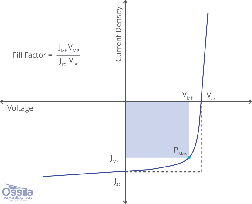
- From this I-V curve, the software extracts key metrics (VOC, JSC, FF, MPP) and calculates power conversion efficiency.
- It will do this for every pixel selected and for automated systems, will cycle through these automatically.
- All values are shown in the display window, and saved in csv files (if selected).
- Lifetime Measurement
- The Lifetime measurement software takes I-V curves at given intervals over a set time period to track device performance.
- It can do this for multiple pixels on a device, taking the I-V curves sequentially.
- The plots will show VOC, JSC, FF and PCE over time.
- Maximum Power Point Tracking
- The MPP software will take an initial J-V sweep and calculate the maximum power point.
- Then, the system will measure the power drawn at the max power point voltage (VMPP) and at values above and below this voltage (defined by voltage perturbation entered).
- Whichever voltage results in the most power output is defined as the holding voltage for the next measurement.
- This iterative process tracks solar cell performance while trying to maximize efficiency.
- This process is similar to operational conditions for solar panels.
- Stabilized Current Method
- In stabilized current methods, the device is held at a set operational voltage, and resultant current is tracked.
- This is a straightforward method to assess solar cell performance over time.
- This method can account for an initial drop off or burn-in. Allowing the current to stabilize gives a more accurate performance efficiency.

Download our Solar Cell I-V Software
Explore Our Resources
 Interpreting J-V Curves: Insights into Solar Cell Performance
If you work in any solar cell research, you know that achieving optimal device performance can be challenging. There are many factors which can hinder your device performance including:
Read more... Analyzing and Improving Solar Cell Metrics: FF , VOC and JSC
Device metrics are extracted from current-voltage curves (J-V curves) and are vital in determining how efficiently your device is converting sunlight into electricity. They can also be extremely helpful in diagnosing problems in your device.
Read more...