Solar Cell J-V Curve: How To Measure IV Curve of A Solar Cell
When it comes to testing the performance of solar cells, accurate measurements and reliable equipment are essential. The fundamental way to test your solar cell performance is by taking a current-voltage (I-V or J-V) measurement. The I-V curve provides valuable insights into a solar cell's efficiency, power output, and more generally electrical characteristics within the device. If you are conducting research into PV materials, understanding how to measure and interpret J-V curves is crucial in assessing device performance – but also for troubleshooting potential issues within your devices. In this article, we will guide you through the steps required to measure I-V (J-V) curves using various Ossila testing equipment.
IV Curve vs JV Curve: What's the Difference?
The terms 'I-V curve' and 'J-V curve' are frequently used when measuring the current-voltage graphs of solar cells. However there is an important distinction between these two measurements.
In the context of solar cells, I refers to the absolute current produced by a specific solar cell device. However, the absolute current a solar cell device produces depends on its active area. Therefore output current is often normalized by dividing I by the devices active area, A, outputting current density, J.
Short-circuit current density (JSC) is used to calculate a solar cell's power conversion efficiency (PCE). The fact JSC is normalized to a devices active area means it can be used to easily compare results from different solar cells.
Doing an I-V curve measurement and J-V curve measurement is basically identical. Most solar cell IV measurement software, such as the Ossila Solar Cell IV software, will ask you to input device active area. This means the output measurement is given as a JV curve from which device metrics can be easily worked out.
Solar Simulator Setup
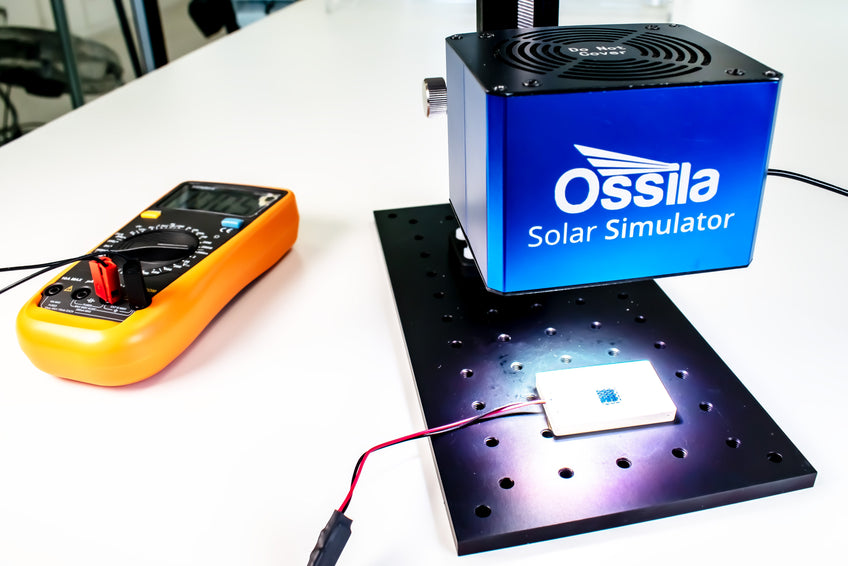
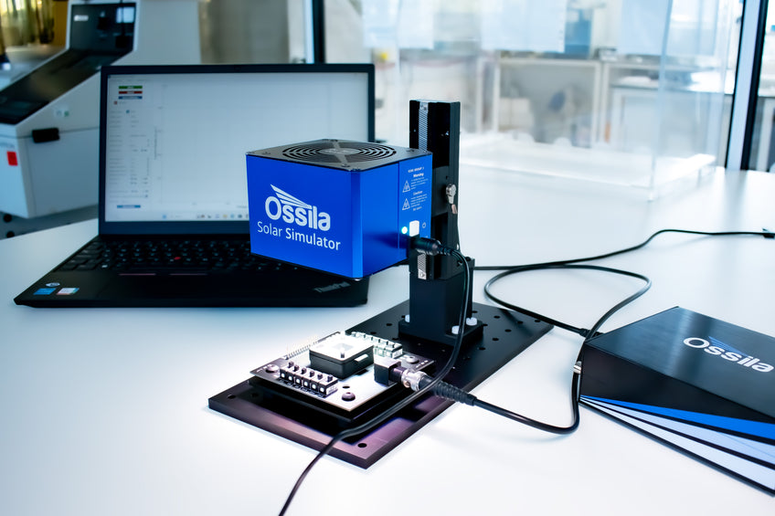
Firstly, you must ensure the correct positioning of your testing system under your solar simulator. Our automated Automates Solar Cell Testing Kit is a comprehensive solution that eliminates the hassle of positioning and calibration your testing equipment. However, you may prefer to use the manual Manual Solar Cell Testing Kit – which allows you to use multiple testing boards compatible with different substrates. If you are using the manual kit, you will need to position the light source correctly to ensure 1000 W/m2 (or 1 Sun) illumination. You can use a reference solar cell to check this calibration.
Positioning your Device
If you are using a non-automated testing set-up, you need to ensure that your device is positioned correctly under the solar simulator. For the Ossila Solar Simulator, we recommend that the surface of your device be 8.5 cm away from the light source – but you may wish to check this distance with an external calibration method.
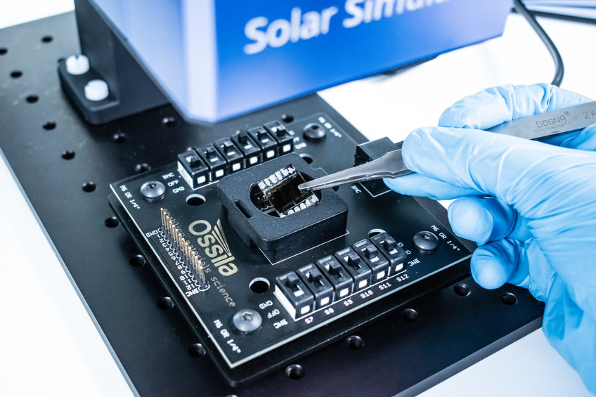
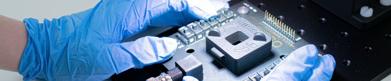
Once your testing board is in the correct position, place your device into the holder (either in the Ossila Push-Fit Test Board or the Solar Cell I-V Test System).If your devices use a transparent substrate then you need to place the device "face down" into the holder. You can use silver paint to create a stronger electrical contact between the device contacts and the testing pins.
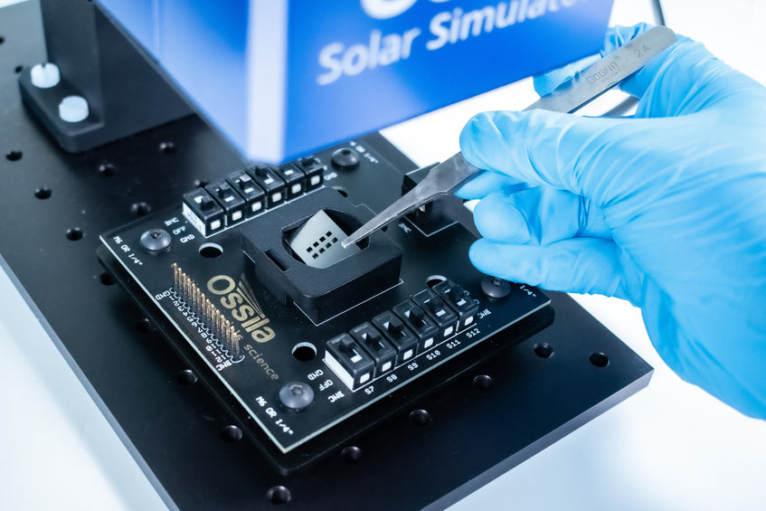
When your device is in place, position your chosen aperture mask over the device. This aperture mask will ensure that your pixels have a well-defined device area – which is important for measuring current density accurately. In the Ossila Solar Cell Test software, you will need to enter device area. The aperture testing mask used here is compatible with 8-pixel devices and has an area of 0.0256 cm2 per pixel.
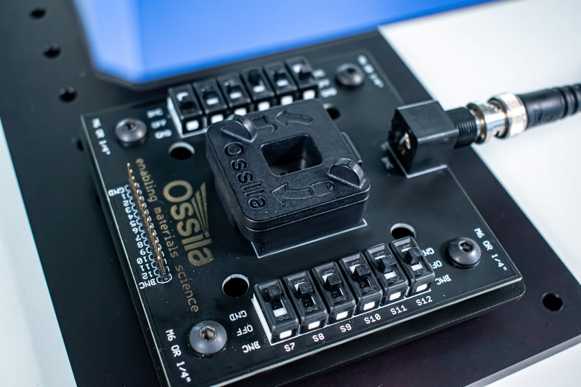
Then use the push-fit bracket to secure your device and mask in place. This will put a small amount of pressure onto the device, creating firm contact between your device and the testing pins. You should now be ready to start measuring devices.
The Automated IV testing system is compatible with a specific substrate type (the standard for this is the S211 substrate). Therefore, these systems are generally compatible with one type of pixel layout. You should pick the Automated Testing system with the substrate option that is compatible with the device type you make the most.
If you are using the Manual Testing System, you will need to manually switch on each pixel on the Push-Fit Test Board. For an 8-pixel configuration with standard architecture, pixels S1, S6, S7 and S12 will be your ground (or "GND") contacts, and you will switch the other connections to from "OFF" to "BNC" one by one to measure the JV sweep of each pixel. Alternatively, you can measure switch multiple pixels to "BNC" at the same time to measure over a larger device area (for example in 1-pixel devices). However, if you are doing this, you will need a different aperture mask and you will need to enter the appropriate device area for this measurement.
Taking Current-Voltage Sweeps with the Ossila I-V Solar Cell Software
The Ossila Solar Cell IV software makes it quick and easy to measure J-V sweeps. Its user-friendly interface means that all you need to do is enter some information about your device (how many pixels, pixel area) and some measurement variables (voltage range, voltage increment and settle time), and press go.
If you are using the Automated system, the software will run through the pixels and measure a J-V sweep for each pixel. If you are using a testing board (the manual testing system), then you need to turn the pixels on when prompted.
As each J-V sweep is measured, the software automatically calculates and displays device metrics in the display box on the right. It will also show the device measurement time and the voltage scan rate on the display screen in the bottom right corner.
If the "Save After Measurement" function is on, this data will automatically be saved in the assigned folder with the device name. This will save three files:
- One containing the J-V sweep information which you can plot separately.
- One containing the calculated device metrics.
- One containing the measurement settings for that measurement.
Whether you are using the Automated or Manual Solar Cell Testing Kit or if you are incorporating individual Ossila components into your own testing configuration, we have developed highly calibrated equipment at an affordable price. This is part of our mission to make conducting solar research as easy and accessible as possible. With our streamlined setup, accurate positioning, and user-friendly software, you can focus on your research and achieve reliable results.
Solar Simulator