How to Check Solar Simulator Calibration
Jump to: How To Calibrate A Solar Sim | Irradiance vs. Spectral Match | Initial Calibration | Checking Irradiance | Standard Photovoltaics | Photodiodes
It is important to ensure that that a solar simulator is outputting a consistent spectral output. Different solar simulators will have different bulb lifetimes, and the spectrum delivered by a solar simulator may change over time - both in the short and long term. Therefore, you should check the calibration of your solar simulator periodically. This way you can ensure that your solar simulator is delivering calibrated light close to the AM1.5G spectrum.
Using the Reference Solar Cell to Check your Solar Simulator
-
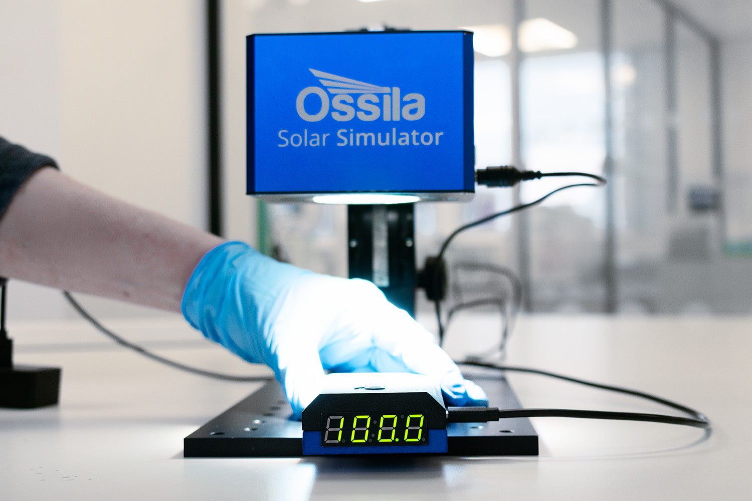
Turn on your solar simulator and allow the light source to warm up. LED Solar Simulators can achieve 1 Sun irradiance almost immediately, but it is good practice to wait a few minutes to ensure stable output. For arc lamps systems, you may need to wait 30 minutes until consistent output is guaranteed.
-
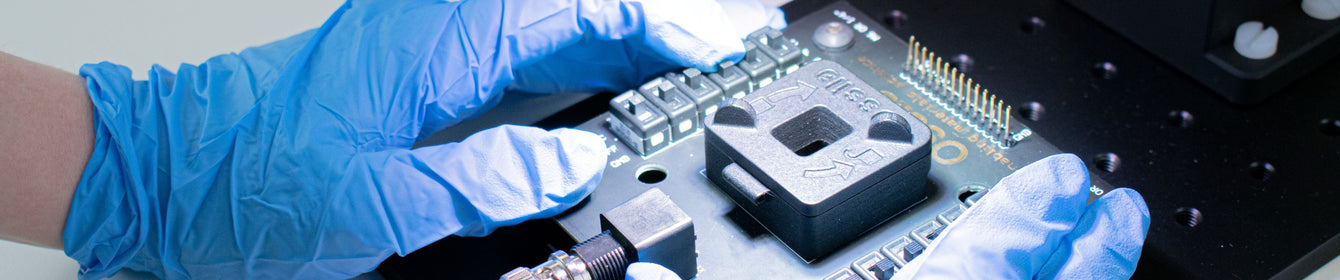
Place the reference solar cell where your device will be. Try to be as accurate as possible in this, considering both its lateral placement and distance from the light source. The Ossila Solar Simulator should exhibit 1 Sun illumination 8.5 cm from the solar simulator base.
-
Check the output of your reference cell. If it reads the defined standard output for 1 Sun, your positioning is correct and you can begin testing your devices.
-
If the reference cell reads out a different value, then you can adjust the height, position or power supply of your light source until the reference cell reads the standard value.
NOTE You should not have to vary the height or power output too much to achieve 1 Sun irradiance.
If you are having to vary this largely, this could mean the bulb is reaching the end of its lifetime and needs to be changed. For an arc lamp, this will usually be after 1000 hours use. For LED light sources, this might be >10,000 hours.
Irradiance vs Spectral Match
The accuracy of a solar simulator can be defined in terms of its spectral match or irradiance. The average irradiance of the solar spectrum is 1000 W/m2 (100 mW/cm2 or 1 Sun), and most solar simulators try to meet at least this standard. The irradiance of a solar simulator can be easily measured using a standard silicon reference cell or photodiode calibrated to give a consistent output at 1 Sun.
However, there can be changes in the spectral distribution of your solar simulator over time, which could be missed in irradiance measurements. Unfortunately, to accurately measure spectral drift, you will need to check solar simulator emission with a highly calibrated spectrophotometer. You can perform an approximate reading using a spectrometer - but this will be a qualitative measurement rather than for direct calibration.
The chance of changes in spectral output increase with age of lamp, so it is important to bear in mind bulb lifetime. If you are using a lamp with a short lifetime, such as an arc lamp, make sure its performance is monitored and that the bulb is changed when necessary.
Initial Calibrations
The goal of any solar simulator is to accurately replicate the solar spectrum, so it is vital that the light produced by your solar simulator is thoroughly and accurately characterized before use. All solar simulators are classified according to well-defined calibration standards, such as the IEC 60904-9:2020 International Standard.
This initial calibration is the job of solar simulator manufacturers. All Ossila Solar Simulator Lamps are calibrated with an 8.5 cm working distance using a broadband spectroradiometer. A spectroradiometer can measure the intensity, power and irradiance of light at different wavelengths and is calibrated so that it can be very accurate in these measurements. This measurement can give you the spectral power distribution (SPD curve) of a light source.
Every one of the Ossila Solar Simulator lamps is thoroughly calibrated before distribution to ensure that it meets IEC 60904-9:2020 calibration standards. We ensure that it meets AAA grade classification over an area of 15 mm area diameter and an ABA classification over a 25 mm area. You can therefore be assured that your Ossila LED Solar Simulator Lamp will arrive fully calibrated and ready to use.
Checking Spectral Output

While the manufacturer performs the initial calibration, you may wish to check the measurement of your solar simulator once you have it set-up in your laboratory. If you are using a solar simulator with a variable height stand, you will need to ensure the solar simulator is set up at the correct working distance. The Ossila Solar Simulator has a working distance of 8.5 cm – meaning that the irradiance is 100 mW/cm2 (1 Sun) 8.5 cm from the base of the solar simulator. Any slight shift in this distance will affect the intensity of light on your sample and may influence your measured device metrics.
The output of your solar simulator may change over time. Depending on the type of light source, this change will happen at different rates. Fluctuations can happen over a short time scale (over the course of one of several measurements). An example of this short-term fluctuation is if the lamp exhibits spectral flicker. Alternatively, this fluctuation may happen over a longer period of time (over a period of weeks or months). For example, as arc lamps age, they exhibit an effect known as spectral drift.
LED lamps tend to have much longer lifetimes that their arc lamp alternatives, so this shouldn't be as much of an issue with the Ossila Solar Simulator. However, as mentioned before when using the variable height stand, you may wish to check the relative position hasn't changed over time - even millimeters of movement can make a difference.
It is good practice to check the calibration of your solar simulator regularly, whatever light source you use.
To check solar simulator calibration, you can use a calibrated reference solar cell, which outputs a standard value at 1 Sun. A reference solar cell can use a standard photovoltaic device, a calibrated photodiode or light sensor to measure track the relative performance of your solar simulator over time.
Using Standard Reference Photovoltaics
The most fail-safe way to check the output spectrum of your solar simulator is using a stable device of known photovoltaic performance. This reference device should ideally be the same type of PV device as the device you are testing. However, the most common choice of reference cell is Silicon PV, due to its dependable performance.
The reference cell output is often calibrated to read 1.00 or another standard measurement under a 1000 W/m2 irradiance at 25 °C. This cell is encapsulated with a protective layer to prevent damage to the device and ensure long cell lifetime.
If you are having to vary this largely, this could mean the bulb is reaching the end of its lifetime and needs to be changed. For an arc lamp, this will usually be after 1000 hours use. For LED light sources, this might be >10,000 hours.
Photodiodes
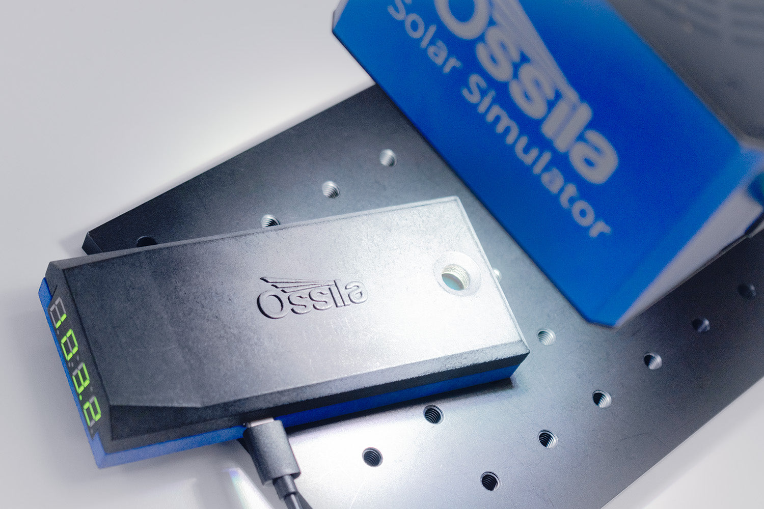
You can also use photodiodes to track relative performance, such as with the Ossila Reference Solar Cell.
Photodiodes are small photojunction devices that contain a diode. Under reverse bias, photodiodes will exhibit a reverse-leakage of electric current. This reverse leakage is increased massively once the device is illuminated, which leads to increased current flow through the device. The current produced is proportional to the intensity of light onto the device surface. By plotting current output against light intensity for a particular photodiode, you can define the relationship between these properties for that one specific device.
The actual current output of a photodiode varies depending on the type of photodiode you are using. There can even be some discrepancy between photodiodes of the same type. Therefore, you cannot use these devices to objectively measure irradiance unless you have seen how that particular photodiode performs under a calibrated 1000 W/m2 light source at a set distance. Every Ossila reference solar cells is calibrated under our classification AAA Solar Simulator, so they are suitable for measuring 1 Sun under various solar simulators (withing 400 – 1100 nm).
Without this calibration, you can use photodiodes to track the relative performance of your solar simulator. To do this you will need to measure current output at 1 Sun light intensity - when your solar simulator is first set up in your lab. You can then repeat this measurement at any time to check if the irradiance of your solar simulator has changed. However, without proper calibration these measurements are very limited.
Solar Simulator

Learn More
 Solar Simulator Classification and Calibration
Solar simulators must be evaluated according to one of the three standards, and comply with the specifications set out within.
Read more... Solar Simulator Irradiance and Spectral Mismatch
Solar simulators generally attempt to replicate the standard AM1.5G spectrum which has a total integrated irradiance of 1000.4 W/m2 over the wavelength range of 280 nm – 4000 nm.
Read more...