


Gas Diffusion Electrodes (GDE)
Jump to: What Is A Gas Diffusion Electrode? | GDE Layers | GDE Properties | Gas Diffusion Electrode Applications | More Resources
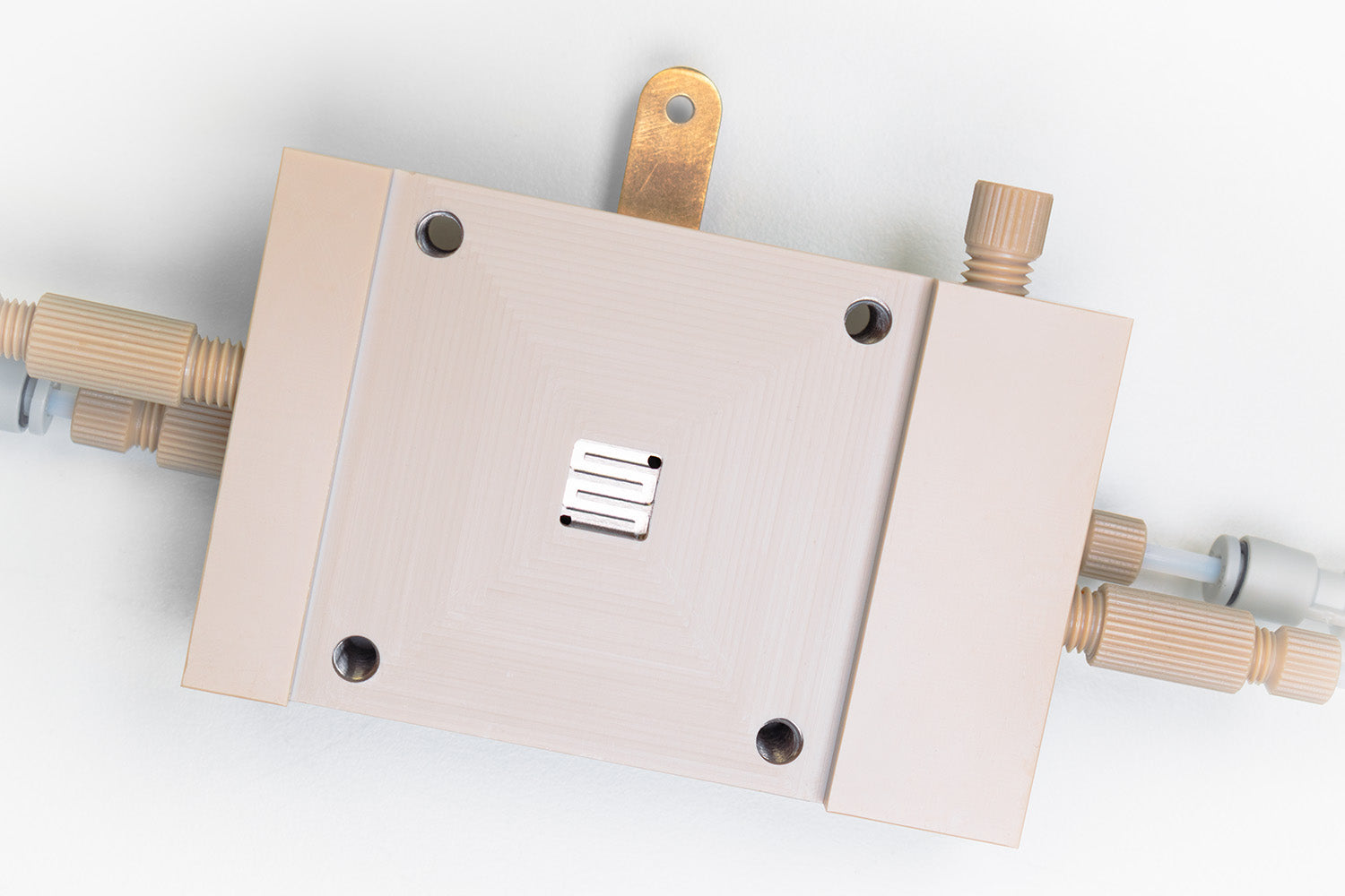
A gas diffusion electrode (GDE) is a porous, multilayer electrode that facilitates the meeting of a gaseous reactant, a liquid electrolyte, and a solid catalyst at a single, well-defined interface, known as the triple-phase boundary (TPB), promoting the desired electrochemical reaction at the interface.
This solves a basic mass-transport problem: gases such as CO2, H2, O2, and N2 dissolve poorly and diffuse slowly in liquid electrolytes so reactions relying on dissolved gas alone are limited by how much gas can reach the catalyst (main limitation in standard cells against achieving high current densities). GDEs get around this by feeding gas from behind the electrode, cutting transport distances from millimetres to microns and enabling current densities liquid-fed systems can't reach.
Originally developed for chlor-alkali production and fuel cells, GDEs have since expanded to be used in most gas-fed electrochemical energy technologies. Fuel cells, water electrolysers (PEM, AEM, BPM), CO2 electrolysers (CO2RR), metal-air batteries (Lithium-air and Zinc-air commonly), and nitrogen reduction systems (NRR) all use some variant of the same layered structure, tuned to the specific gas, electrolyte, and reaction involved.
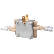
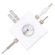
Browse Gas Diffusion Electrode Cells
What Is A Gas Diffusion Electrode?
At the triple-phase boundary:
- The gas arrives through interconnected pores.
- The electrolyte wets the catalyst from the opposite face.
- The electrons move through the conductive carbon (in most cases) backbone.
The reaction rate depends on how much of this TPB is active at any moment, which is why GDE design, rather than catalyst chemistry often decides whether a promising lab result can translate into a workable device.
Rather than a fixed geometric line, the triple-phase boundary is better understood as a dynamic, unevenly distributed microenvironment. This will be affected by local pH, ion concentration, and wettability, which all vary within the pore network and shift during operation. Due to this, GDE performance can drift over the course of an experiment, even when the nominal operating conditions as current, flow rate, and electrolyte concentration kept constant.
GDE Cell Design: Layer by Layer
A GDE is built from three functional layers, bonded into a single porous stack. These are the substrate (e.g. carbon cloth), a microporous layer and a catalyst layer. The substrate and microporous layer together make the gas diffusion layer. The GDL is the mechanical and electrical backbone of the electrode.

- The substrate in a GDE provides a porous matrix for the gas to migrate through while still being conductive enough to perform as an electrode. The open structure allows the gas to easily flow through towards the catalyst. This facilitates a consistent flow of gas towards and over the reaction site, carrying reactants to the triple phase boundary and products away from it. However, this layer must also maintain high conductivity and reasonable tensile strength.
- The microporous layer acts largely as a barrier layer, preventing the migration of water into the substrate. Flooding into the mesoporous structure will prevent gas flow, limiting GDE functionality. However, layer can limit gas diffusion and conductivity. This layer must be chosen carefully, to smooth pore-size distribution, improve electrical contact, maximize gas flow and preventing product water from flooding the GDE.
- The catalyst layer is where the reaction occurs. This material depends on the reaction you are doing. These catalyst particles are often combined with PTFE fibers that connect the catalyst to the microporous layer.
Substates: Carbon vs. Metal Substrates
Carbon paper (non-woven) and carbon cloth (woven) are the default choice for GDE cathodes in CO2RR, PEM fuel cells, and other applications under acidic or neutral systems. However, carbon is prone to corrosion in strongly alkaline or high anodic-potential environment, such as in alkaline electrolysis and some AEM systems. Also, carbon is prone to attacked by oxygen intermediates as singlet oxygen, OH radicals, or by lithium or sodium superoxide forming carbonates. This can passivate the battery cathode surface. Decomposing this passivation requires high charging overpotentials, reducing the Faradaic Efficiency of the system. In such scenarios, metal substrates such as nickel foam, titanium felt or mesh, and stainless-steel mesh are used instead.
| Carbon Paper | Carbon Cloth | Metal Foam / Mesh (Ni, Ti, Stainless Steel) | |
|---|---|---|---|
| Structure | Non-woven, rigid | Woven, flexible | Sintered or woven metal, highly compressible. |
| Stability | Good in acidic/neutral, cathodic use | Same as Carbon Paper | Stable in strongly alkaline or high anodic-potential conditions, and against radical attacks |
| CO2 Supply | Solubility-limited (~33 mM) | Gas-fed, no solubility limit | Gas-fed, no solubility limit |
| Typical Use | CO2RR and PEM FC flow cells, MEAs | Flexible Cells | Alkaline electrolysis, metal-air cathodes, AEM systems |
Microporous Layer (MPL)
This is usually a thin carbon-black coating sits between the GDL and catalyst layer. This smooths the pore-size distribution, regulating the amount of catholyte wetting, while maintaining a reasonable gas diffusion and electrical contact.
Catalyst layer
Reaction catalyst nanoparticles are dispersed with an ionomer or binder to create a catalyst layer that can be directly coated onto the MPL or onto a membrane.
The selection of catalyst materials is application specific. Noble metal/ metal oxide catalysts, like Pt and RuO2, are industrial benchmarks for catalysing HER and OER reactions across applications. However, transition metal oxides and other derivatives perform competitively in alkaline medium in AEM electrolysers related to water splitting,, metal-air batteries and related energy applications. The catalyst selection is more complex in CO2RR as the selection of catalyst (e.g. Cu, Ag, Sn) is based on the medium and the intended end product.
PTFE hydrophobicity treatment
PTFE is applied to the GDL and/or MP, to control wetting (primarily on carbon-based substrates) to make sure the electrolyte is kept close to the tri-phase boundary while preventing flooding into the GDE blocking the gas diffusion pathways.
However, too much PTFE blocks GDE porosity and starves the catalyst of electrolyte contact, while also adding a significant resistance against electron transport. Hence, it is important to properly optimize the amount of PTFE. Alongside PTFE, other materials such as PVDF and FEP can be used instead, offering similar water-management behaviour with different cost and chemical-resistance trade-offs. Metal substrates manage wetting differently, largely through pore geometry and surface coatings rather than PTFE loading.
Gas Diffusion Electrode Properties
-
Porosity
This governs gas throughput: too low restricts mass transport, too high weakens mechanical integrity.
-
Hydrophobicity
This balances gas access against electrolyte flooding.
-
Catalyst Loading
More catalyst doesn’t always guarantee better performance. Excess loading adds resistance and can bury active sites.
-
Ionomer content
Extends the reaction zone by improving ionic contact, but can block gas pores if overused..
GDE Applications Across Energy Systems
The fundamentals of GDE use are shared across applications, but operating requirements differ considering the nature of the reaction and the reaction constraints. A GDE that is optimized for one reaction may not the best fit for another.
One way to choose GDE components is according to whether the reaction consumes or produces gas at the electrode. Gas-consuming reactions such as CO2RR, NRR, and ORR typically need continuous reactant delivery and a stable, extended triple-phase boundary. The GDE cell requires hierarchical pore networks and controlled hydrophobicity.
Gas-evolving reactions as water electrolysis and other anodic processes, generally face the opposite problem: rapid bubble detachment and mechanical robustness matter more than reactant supply. This is because trapped bubbles block ionic conduction and accelerate delamination.
No single pore design serves both regimes well, which is why electrode architecture is usually reaction-specific rather than universal. The following table lists key requirements for few of the common applications
| Application | Problem | Cell Requirement | Feature Benefits |
|---|---|---|---|
| CO2RR | Salt crystallization blocks gas flow, flooding the cell and triggering HER | Salt-Tolerant Porosity | Extends electrolyzer continuous operational lifespan from hours to thousands of hours. |
| CO2RR | Massive carbon loss via carbonate crossover & low reactant density at the catalyst. | CO2 Selective Transport | Drives up carbon utilization efficiency and optimizes product selectivity (e.g., CO, Ethylene). |
| HER | High bubble adhesion traps H2 gas on the surface, making catalyst sites unavailable. | High gas throughput (bubble management) | The detachment of microbubbles, keeping the catalyst surface completely clear, enhancing the efficiency and avoid voltage spikes. |
| HER | High activation barriers waste electrical energy as heat, causing severe cell degradation and extensive electricity costs. | Low Overpotential | Maximizes the system's voltage efficiency, enabling high-rate hydrogen production with minimal power consumption. |
| ORR / fuel cells | Chemical oxidation, electrosorption, and local temperature spikes degrade the PTFE binder over time. This makes the pores hydrophilic, causing gradual electrolyte flooding, mass-transport failure, and premature cell death. | Long-term hydrophobic stability | Guarantees long-term stability, continuous operation by preventing liquid breakthrough, maintaining permanent gas channels, and preserving high product selectivity |
| Metal-air batteries | The degradation of GDE forms biproducts deactivate the electrode surface, clog pores, and require higher charging overpotentials to decompose reducing the efficiency. | Bifunctional stability (ORR + OER) | Long stability across hundreds to thousands of repeated charge/discharge without degrading |
| NRR | Excess liquid electrolyte floods the catalyst surface, providing immediate access to protons to promote HER over NRR. | Proton-Stray Limiting Wettability / High Selectivity | Restricts bulk water contact while stabilizing an ultra-dense, gas-rich triple-phase boundary, forcing the catalyst to prioritize NRR over HER. |
| NRR | Low N2 gas diffusion flux or high pore tortuosity starves the active sites of nitrogen, causing a kinetic barrier. | High-pressure N2 supply and High Interfacial Concentration | Ensures a constant, high-pressure supply of N2 directly at the catalytic interface, pushing the equilibrium toward ammonia (NH3) synthesis. |
This list isn't exhaustive, and the same architecture also underpins electrochemical hydrogen peroxide synthesis (via the two-electron ORR pathway) and its use in electro-Fenton water treatment, alongside longer-established industrial uses such as chlor-alkali and ozone production. The same porous, controlled-wettability design that prevents flooding in CO2RR is what governs oxygen delivery and radical generation in these processes too.
Learn More
 In-Situ Raman Spectroscopy
In-situ Raman spectroscopy is a non-invasive technique which combines electrochemistry and Raman spectroscopy. This technique can probe interactions, product formation and other processes that occur at electrode interfaces in real time. Standard ex-situ Raman measurements can only capture the stable end states after an electrochemical process is complete. However, in-situ Raman measurements allow you to observe chemical and structural transformations occurring at the electrode surfaces in real time.
Read more...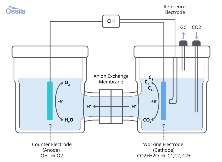 CO2 Reduction (CO2RR)
As investment in carbon capture technologies continues to grow, increasing attention is being paid to carbon utilization. Namely, how are we going to reuse this carbon to produce useful products? CO2 reduction presents a way of using this carbon to produce useful compounds used in fuel and chemical feedstock.
Read more...Contributing Authors
Written by
Product Development Electrochemist
Diagrams by
Graphic Designer
References
- Advances in bifunctional electrocatalysts towards high-performing Li-air batteries, S. Karunarathne et al., Journal of Power Sources (2024)
- Gas diffusion electrodes for sustainable energy conversion and..., Y. Zhang et al., Green Energy & Environment (2026)
- Gas diffusion electrodes (GDEs) for electrochemical reduction of..., H. Rabiee et al., Energy Environ. Sci. (2021)
- Systematic screening of gas diffusion layers for high..., A.A. Samu et al., Communications Chemistry (2023)
- Gas Diffusion Electrode with Microporous Layers of Hydrophobicity..., Q. Wan et al., ACS Sustainable Chem. Eng. (2023)