


Troubleshooting CO2RR
Flow Field Material Selection | Flow Field Geometry | Troubleshooting
Practical hardware decisions determine whether a CO2RR electrolyzer operates reliably at elevated current density. These include flow field plate material selection, flow field geometry, and the operational failure modes such as salt precipitation, GDE flooding, membrane degradation, and catalyst contamination that account for most lab-to-scale-up failures.
Browse CO2RR Cells
Gas Diffusion Electrode Flow Cells
Gas Diffusion Electrode Flow Cells
Explore our range in Gas Diffusion Electrode Flow Cells
Flow Field Plate Material Selection
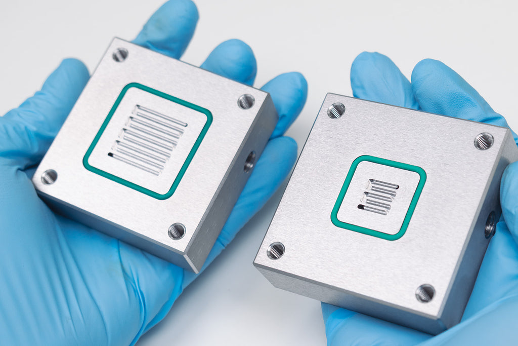
Flow field plates and current collectors serve four simultaneous functions:
- Uniform reactant distribution
- Electron conduction
- Mechanical support of the membrane/GDE stack
- Electrochemical stability under both oxidative (anode) and reductive (cathode) conditions
These functions impose conflicting material requirements, and no single material satisfies all of them across all cell types. Material selection must therefore be driven by the specific membrane chemistry, electrolyte pH, and operating current density.
The central risk specific to CO2RR is catalyst contamination from plate corrosion. Unlike water electrolysis, CO2RR catalysts, particularly copper, bismuth, and tin are acutely sensitive to trace metal contamination. Iron leaching from stainless steel, nickel leaching from Ni-plated plates, and chromium dissolution from steel all suppress CO2RR activity and shift selectivity toward HER within hours of exposure. This makes material selection a higher-stakes decision in CO2RR than in comparable hydrogen electrolysis applications.
Cathode Flow Field Material Selection
For most laboratory-scale CO2RR work using alkaline or near-neutral electrolytes, high-purity graphite is the most practical cathode plate material. It is:
- Chemically inert across the full pH range
- Electrically conductive
- Abundant and cheap
- Readily machinable into custom flow field geometries
Its principal limitation is mechanical: graphite is brittle and susceptible to cracking under non-uniform bolt torque. It also becomes gas-permeable at pressures above approximately 5 bar, limiting its use in pressurized MEA stacks. Carbon composite plates (polymer-bonded graphite) address the brittleness issue at the cost of moderately lower conductivity. These cathodes are good for larger active-area flow cells, where mechanical robustness matters more than minimizing interfacial contact resistance. Gold-plated titanium is a far more stable material choice compared to stainless steel or nickel. It has the stability of titanium without risking the formation of a TiO2 insulating layer that forms on the pure material. However, gold can catalyze CO production if the plate surface is exposed through non-perfect sealing, which can artificially increase the CO production.
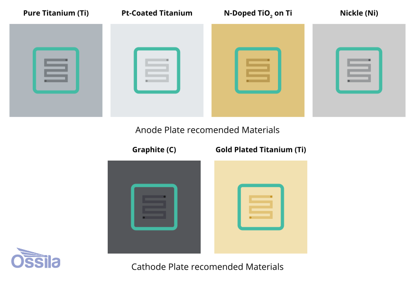
Anode Flow Field Material Selection
At the anode, material selection is governed primarily by the electrolyte pH imposed by the membrane. In alkaline anion exchange membrane (AEM) systems, nickel or nickel-plated steel is the standard choice: nickel forms a stable, catalytically active Ni(OH)2/NiOOH passive layer under OER conditions and is compatible with the cost constraints of research-scale hardware.
Stainless steel 316L is an acceptable lower-cost alternative for the cathode side of AEM cells, provided the system contains no fluoride ionomer degradation products from Nafion or PFSA-based ionomers, as they will cause exponential pitting corrosion in any stainless-steel component in contact with the electrolyte, with dissolved Fe2+/Fe3+ poisoning copper and bismuth catalysts within hours.
In acidic environments, such as PEM/CEM cells or the anode side of BPM cells, titanium is the only realistic base metal option as its native TiO2 passive layer resists strong acid OER conditions. However, TiO2 is electrically insulating and therefore must be coated, usually with platinum, gold, titanium nitride (TiN), or niobium/tantalum multilayers. TiN-coated titanium now meets the US Department of Energy's 2025 targets for interfacial contact resistance (<10 mΩ·cm2 at 140 N/cm2 compaction) and corrosion current density (<1 μA/cm2) at substantially lower cost than platinum-coated alternatives.
| Material | Environment stability | Electrical conductivity | Corrosion resistance (cathode) | Corrosion resistance (anode, acid) | Corrosion resistance (anode, alkaline) | Typical use | Key pitfalls |
|---|---|---|---|---|---|---|---|
| Graphite (high purity) | Acid, alkaline, neutral | High (300-500 S/cm) |
 Chemically inert under reduction Chemically inert under reduction |
Resists acid oxidation at moderate potential |
Stable in KOH |
Cathode (all cell types); anode in alkaline AEM | Brittle, fractures under uneven compression. Machining creates microcracks. Permeable to gas at >5 bar. Not suitable for high-pressure MEA stacks. |
| Titanium (Grade 1 or 2) | Acid, alkaline, neutral | Medium (2.4 S/cm bulk; high ICR at surface) |
Passive TiO₂ layer stable under reduction |
TiO₂ passive film resists strong acid OER |
 TiH₂ embrittlement; forms insulating hydride layer TiH₂ embrittlement; forms insulating hydride layer |
Anode in PEM/CEM and BPM (acid side); PTL substrate | Native TiO₂ is electrically insulating, must be coated (Pt, Au, TiN, or N-TiO₂). Avoid in alkaline, hydride formation degrades plate. Expensive. |
| Pt-coated Titanium | Acid (primary use) | High: Pt layer highly conductive |
Pt stable under mild reduction |
Pt resists dissolution up to ~1.5 V vs RHE |
Pt dissolves at high alkaline OER potentials over time | Anode in PEM/CEM electrolyzers; high-end MEA stacks | High cost. Pt can delaminate from Ti substrate over time. Avoid in strongly alkaline, Pt dissolution accelerates above pH 13. |
| Stainless steel 316L | Neutral to mildly alkaline | High (~1.4 S/cm) |
Cr₂O₃ passive film stable under reduction |
Pitting corrosion in Cl⁻ or fluoride-containing acid |
Cr passive film stable to ~pH 12; fails at higher pH | Cathode plate in AEM cells; anolyte side at mild pH | Not suitable for acidic anode environments. Fluoride from ionomer degradation causes exponential dissolution (pitting). Fe contamination poisons Cu/Bi catalysts, critical concern. Ni leaching in alkaline degrades membranes. |
| Nickel / Ni-plated steel | Alkaline (primary use) | High |
Stable under cathodic protection in alkaline |
Dissolves rapidly in acid |
Passive Ni(OH)₂/NiOOH layer, OER active |
Anode and cathode plates in AEM cells; anode in BPM (alkaline side) | Strictly alkaline only. Ni²⁺ leaching in near-neutral or acidic conditions rapidly poisons CO₂RR catalysts. Avoid any exposure to pH <9. |
| Carbon composite (polymer/graphite) | Acid, alkaline, neutral | Medium-High (50-200 S/cm, formulation-dependent) |
No metal dissolution risk |
At moderate potentials |
No alkaline corrosion |
Cathode in all cell types; anode in alkaline MEA | Gas permeability if resin content too low. ICR increases with oxidation of graphite filler at high anode potentials. Swelling in concentrated KOH. Mechanical creep under sustained compression. |
| Ti with TiN or N-TiO₂ coating | Acid (coated surface) | High: coating provides conductivity path | |
TiN resists acid and OER; ICR <10 mΩ·cm² (DOE 2025 target) |
TiN less stable than Pt at high alkaline OER | Anode plate in PEM/MEA cells, lower cost alternative to Pt-Ti | Coating defects expose Ti substrate to acid pitting. Coating adhesion fails if substrate surface not properly activated. Long-term data <5,000 h still limited. |
| Ti with Nb/Ta multilayer coating | Acid | High: Nb/Ta preserve conductivity | |
Corrosion current <1 μA/cm²; meets DOE 2025 target |
Limited alkaline data | High-performance anode in PEM/MEA cells, research use | Very high cost. Deposition process complex (PVD/sputtering). No established commercial supply chain. Primarily in academic and advanced pilot studies. |
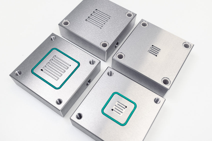
Flow Field Geometry
The geometry of the flow field channels directly controls how uniformly CO2 gas reaches the catalyst layer and how efficiently liquid products and O2 are removed. Poor distribution creates local regions of CO2 starvation (driving HER) alongside regions of product accumulation (driving flooding), even when total flow rates are adequate. Flow field design is therefore not a secondary engineering detail, as it is a primary determinant of Faradaic efficiency uniformity across the active area, and becomes increasingly critical as active area scales beyond 4 cm2.

| Design | Mass transport | Pressure drop | Best suited for | Key limitation |
|---|---|---|---|---|
| Serpentine (standard lab-scale) | Good: continuous flow velocity sweeps channel length, prevents stagnant zones | High: single continuous channel creates large end-to-end pressure differential | CO₂ gas feed at cathode where consistent velocity prevents salt accumulation. Standard for lab-scale MEA cells. | High pressure drop at large active areas. Non-uniform CO₂ distribution across wide plates, center starved vs inlet/outlet. Pressure pulse if gas channels partially blocked. |
| Parallel | Moderate: each channel carries equal flow fraction but flow can bypass blocked channels | Low: short, parallel paths minimize resistance | Anolyte/catholyte liquid flow where low pressure drop is needed and blocking is less likely. Larger active areas in flow cells. | Flow maldistribution: if one channel blocks (salt, bubble), the flow preferentially bypasses it rather than clearing it. Worst architecture for salt-prone GDE cathodes. |
| Interdigitated | Excellent: flow is forced through the GDE pore structure convectively rather than along channels | Very high: forced convection through porous electrode creates maximum resistance | CO₂RR at high current density where GDE mass transport limitation is the rate-limiting step. Best for pushing partial current density. | Very high pressure drop restricts to small active areas. Mechanical stress on GDE, compression-sensitive. Not suitable for fragile catalyst layers or thin GDEs. |
| Mesh / open-face | High: direct access to electrode surface across full area | Minimal | Anode PTL face in MEA cells. Used with Ti or Ni felt PTLs where the mesh is the flow field. | Poor mechanical support. Uneven contact resistance with catalyst layer. Not suitable as cathode flow field where CO₂ distribution uniformity matters. |
Troubleshooting CO2RR Experiments
Salt Precipitation and GDE Flooding
The primary failure mode in alkaline and near-neutral GDE flow cells is bicarbonate and carbonate salt formation. CO2 reacts with cathode-generated OH- to form HCO3- and CO32-, which combine with K+ (or Na+, Cs+) from the electrolyte to form sparingly soluble salts like KHCO3 (solubility ~3.3 M) and K2CO3 which tends to crystallize inside the GDE pore structure. This progressively blocks CO2 gas channels, causing CO2 starvation at the catalyst surface and a cascade shift toward HER.
Operando studies have identified the bicarbonate anion specifically as the critical species: bicarbonate-laden droplets from the catholyte/membrane interface migrate toward the GDE backside, dry out in the gas flow, and deposit crystalline salt. This salt is difficult to remove without disassembling the cell.
To reduce this impact, we would suggest:
- Periodically flushing the anolyte and catholyte with deionized water.
- Operating at lower KOH concentrations (1-2 M rather than 5 M).
- Using a gas diffusion layer (GDL) with larger pore structures (such as woven carbon cloth rather than conventional carbon paper). These can maintain higher FE even when partially flooded by retaining open large-pore gas channels, as the larger pore channels remain unblocked.
- Use forward-bias bipolar membranes that suppress K+ transport toward the GDE.
- Periodically reverse flow direction to dislodge any salts that have formed. Anolyte flow rate is a frequently overlooked variable. In fact, too high a flow rate convectively accelerates K+ transport toward the cathode, worsening precipitation. Alternatively, lower flow rates can cause local electrolyte depletion at the anode.
MEA-specific Issues
In zero-gap MEA architectures, sources of failure shift from salt precipitation (less common without catholyte). Issues with these cells are more likely to include:
Membrane dry out which occurs when CO2 gas flow rate is too high, evaporating water from the membrane faster than the anolyte can replenish it. This causes a step increase in ohmic resistance, detectable as a sudden cell voltage rise at constant current.
GDE flooding from liquid crossover which occurs not from catholyte but from water crossover through the membrane and condensation in the gas channels, particularly at high current densities. At these high currents, there is significant water production from OER and from CO2RR side-reactions.
Uneven compressio which is a critical and underappreciated issue. If the torque applied to flow field plate bolts is non-uniform, the local contact resistance varies across the active area, creating current density hot spots that accelerate local catalyst degradation, membrane thinning, and (in the worst case) membrane pinhole formation. A torque-wrench protocol and defined compression sequence are recommended for any active area above 4 cm2.
Catalyst Contamination
Metal ion contamination from corroding hardware components is a silent failure mode that often presents as catalyst deactivation. For example:
- Fe2+/Fe3+ formation from stainless steel plates can accumulate on copper catalyst surfaces and suppress C2+ production, shifting the selectivity toward H2.
- Ni2+ from nickel plates or membranes suppresses CO2RR broadly and can permanently deactivate Bi and Sn catalysts at concentrations as low as 1-10 ppm.
You can see this contamination as a gradual decline in CO2RR Faradaic efficiency without a corresponding increase in cell voltage. This distinguishes it from mass transport or ohmic failures. However, inductively coupled plasma mass spectrometry analysis of the electrolyte is the definitive test. If Fe or Ni is detected at >1 ppm, check the hardware material and compression seals and replace the catalyst.
Membrane Degradation
AEM membranes degrade under sustained alkaline conditions due to hydroxide attacks on quaternary ammonium cationic groups. This progressively reduces ion exchange capacity and increasing ionic resistance. This will cause a gradual rise in cell voltage at constant current over tens to hundreds of hours, eventually accompanied by a decline in CO2RR Faradaic efficiency as the local cathode environment becomes less alkaline
Membrane pre-treatment protocol can significantly affect both its initial performance and lifetime. AEMs should be equilibrated in the target electrolyte (not water) for at least 24 hours before first use. Do not store AEMs dry once hydrated.
Fluoride contamination from ionomer degradation in the catalyst layer also accelerates AEM degradation and causes pitting in any stainless-steel components in contact with the electrolyte. For this reason, avoid steel using in fluoride-containing systems.
Browse CO2RR Products
Read More
 Electrochemical CO2 Reduction: Cells and Membranes
Electrochemical CO2 reduction has moved decisively beyond proof-of-concept. As by mid-2026, a growing number of companies and national laboratories are operating continuous pilot-scale CO2RR systems, and the field has developed a reasonably clear picture of what needs to be solved at each level: catalyst, cell, stack, and system, before commercial deployment becomes viable.
Read more... In-Situ Raman Spectroscopy
In-situ Raman spectroscopy is a non-invasive technique which combines electrochemistry and Raman spectroscopy. This technique can probe interactions, product formation and other processes that occur at electrode interfaces in real time. Standard ex-situ Raman measurements can only capture the stable end states after an electrochemical process is complete. However, in-situ Raman measurements allow you to observe chemical and structural transformations occurring at the electrode surfaces in real time.
Read more...Contributing Authors
Written by
Product Development Electrochemist
Videography by
Graphic Designer