


Electrochemical CO2 Reduction: Cells and Membranes
Jump to: H-Cell | Gas Diffusion Electrode Cells | MEA Cell | Porous Solid Electrolyte Cell | CO2 Reduction Cell Comparison | CO2RR Membranes
Electrochemical CO2 reduction has moved decisively beyond proof-of-concept. As by mid-2026, a growing number of companies and national laboratories are operating continuous pilot-scale CO2RR systems, and the field has developed a reasonably clear picture of what needs to be solved at each level: catalyst, cell, stack, and system, before commercial deployment becomes viable.
Ossila's modular CO2RR hardware ecosystem, spanning the H-cell, gas diffusion electrode electrolytic cell, gas diffusion electrode electrolyzer, and MEA electrolyzer is designed to support this full progression with standardized form factors (1×1 cm and 2×2 cm active areas) and compatible electrode dimensions, enabling researchers to transition between architectures without rebuilding experimental infrastructure from scratch.
Browse Electrochemical CO2 Reduction Cells
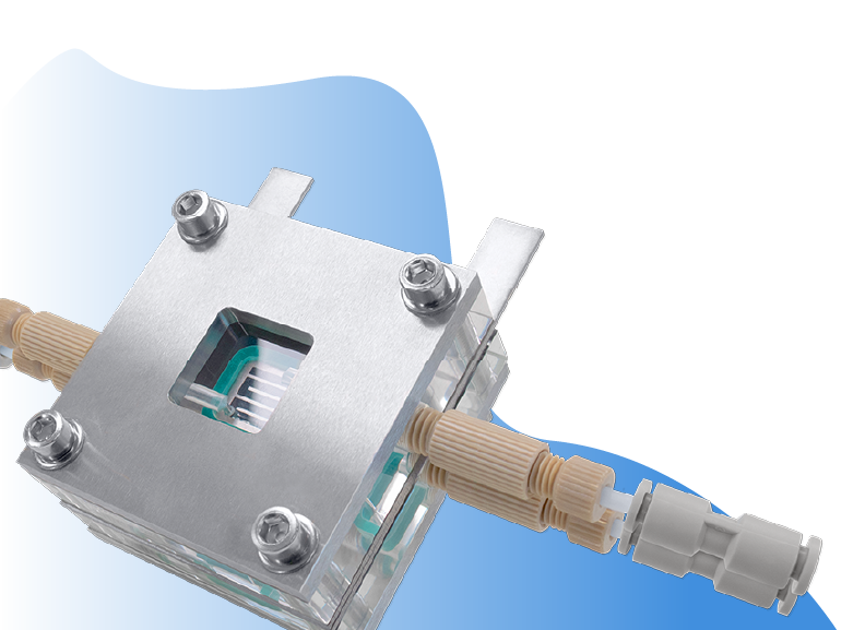
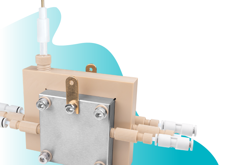
GDE Flow Cells
Gas Diffusion Electrode Flow Cells
Explore our range in Gas Diffusion Electrode Flow Cells
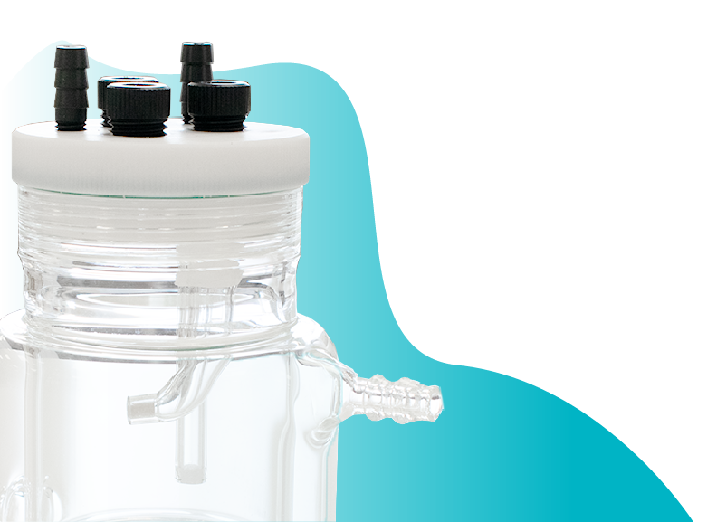
H-Cell for CO2 Reduction
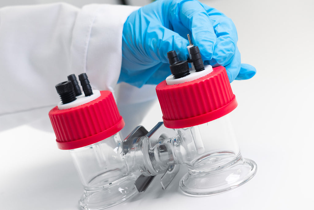
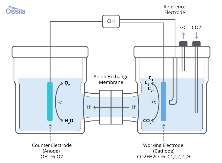
H-cells are one of the most common electrochemical cell designs used in CO2RR. The cell is designed with two compartments, connected via a membrane. CO2 reduction occurs in the cathodic compartment, and the oxygen evolution reaction occurs at the anodic compartment. The membrane allows to transport selected ions, completing the circuit, while blocking the crossover of the reaction products. The membrane can be either a cation exchanging membrane (CEM), a mostly proton exchange membrane (PEM), or an anion exchange membrane (AEM), depending on the electrolyte used for the cell. Except for scenarios of testing acid resistant catalysts, AEMs are preferred as they provide a less favorable environment for the competing hydrogen evolution reaction.
For defining catalyst performance in a simplified, low-cost environment, a H-cell is ideal. It provides full independent control over pH, cation identity, and CO2 partial pressure. However, CO2 solubility in an aqueous electrolyte is only ~33 mM under ambient conditions. Regardless of catalyst quality, current density is limited to 50-100 mA/cm2 before the reaction becomes mass-transport-limited. Selectivity data at these low current densities may not translate to flow cell conditions where local pH, CO2 concentration, and cation gradients are substantially different.
Gas Diffusion Electrode Flow Cells
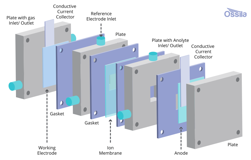
The GDE flow cell is designed to increase the CO2 concentration at the electrode surface. Hence, GDE flow cells solve the H-cell mass-transport issue by delivering CO2 as a gas directly to the back of the catalyst layer. This establishes a triple-phase boundary: gas, liquid electrolyte, and solid catalyst at the reaction interface, eliminating the solubility bottleneck and enabling current densities of 100–500 mA/cm2. To facilitate a high CO2 concentration at the catalyst surface, a porous electrode with a catalyst layer is used as the cathode (and as the anode). This is known as a gas diffusion electrode (GDE). Typically, GDEs are hydrophobic to prevent the flooding the electrolyte out from the cell.
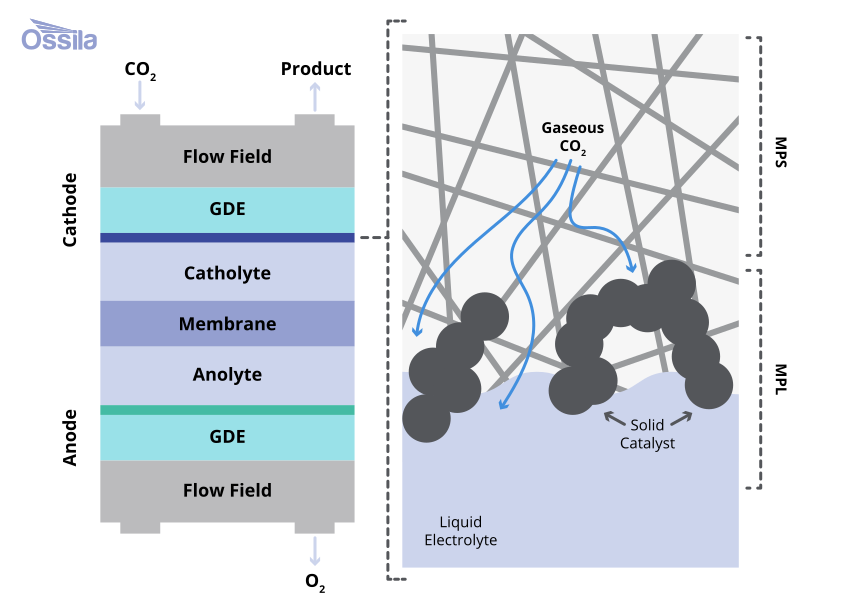
A liquid catholyte (the electrolyte surrounding the cathode) is retained between the GDE and membrane. This provides full independent control over electrolyte composition, pH, and cation identity, maintaining the experimental control needed before committing to a fully integrated cell design.
A GDE flow cell circulates both catholyte and anolyte independently. The anolyte stream removes O2 from the anode surface, maintains uniform membrane hydration, and prevents local pH excursions that degrade OER activity over time. The two streams can be held at different compositions, typically alkaline KOH catholyte to suppress HER, paired with near-neutral KHCO3 anolyte to limit cation crossover and reduce salt precipitation risk.
Bicarbonate salt formation during the reactions blocks the transport pathways and can be a major limitation in the cell architecture. Electrolyte crossover is not eliminated, which lowers the Farraday Operation.

Membrane Electrolyte Assembly Cells
Membrane electrolyte assembly (MEA) electrolyzers and porous solid electrolyte (PSE) reactors are more industry-ready modular architectures, overcoming many bottlenecks identified with the standard H-cell and GDE flow cell designs, achieving a larger current density range.
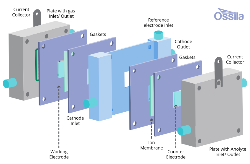
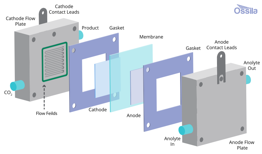
A zero-gap MEA design removes the need for a liquid catholyte layer. The cathode GDE and anode porous transport layer are pressed directly against opposite faces of the membrane, compressing the ionic conduction pathway to only the thickness of the membrane. This results in a step-change reduction in ohmic losses, enabling current densities of 200 mA/cm2 to above 1 A/cm2, which is within commercially viable voltage windows. However, the trade-off is a complete loss of independent electrolyte control at the cathode.
Local pH, ion availability, and water activity are governed by membrane type and anolyte composition, coupled through the membrane. MEA performance is acutely sensitive to cell assembly: ionomer content, GDE compression, membrane pre-treatment, and water management, all interact in ways that are difficult to disentangle post-assembly. MEA architectures are best used once catalyst performance has been characterized within a GDE flow cell.
The dominant carbonate crossover problem remains the most significant barrier to high single-pass carbon utilization efficiency in zero-gap designs. This is when in AEM-based MEAs, CO2 reacts with hydroxide to form bicarbonate that migrates to the anode and is vented as CO2 mixed with O2.
Porous Solid Electrolyte Reactor
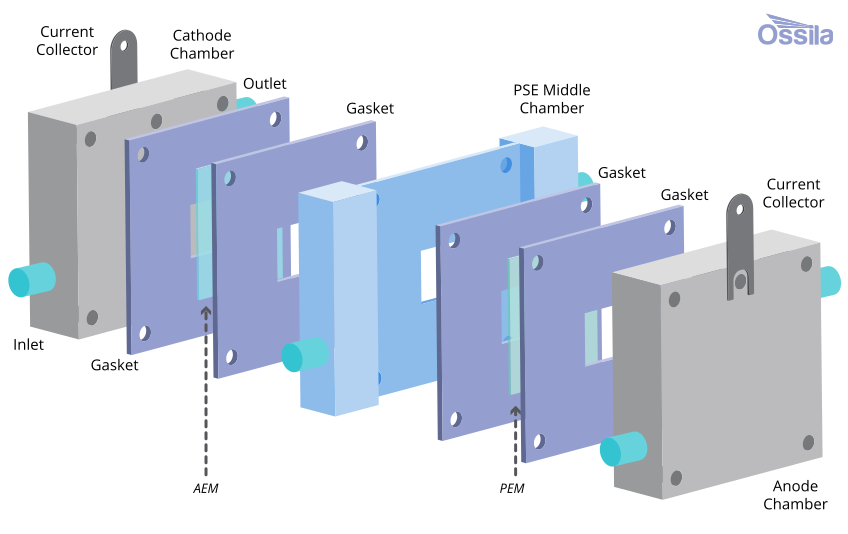
The porous solid electrolyte (PSE) was recently developed to respond to the carbonate crossover issue. The PSE inserts a permeable, ion-conducting sulfonated polymer layer between the cathode and anode to act as a chemically active buffer zone. Crossover carbonate entering this layer encounters protons that have been generated at the anode. This carbonate is converted back to CO2 gas at high purity, which is recycled directly to the cell input, reducing reaction losses. As demonstrated in recent studies, this approach has recovered over 90% of crossover CO2 at purity above 99% while sustaining over 90% CO Faradaic efficiency.
The concept has since extended to reactive carbon capture: feeding bicarbonate solutions as the direct output of alkaline CO2 capture contactors into the PSE layer allows CO2 regeneration and electrochemical reduction to occur simultaneously.
This method achieves high selectivity, Faradaic efficiency, and ~95% CO2 recovery efficiency without a separate desorption stage. This collapses the conventional three-step capture-regenerate-reduce sequence into one integrated reactor. The PSE architecture currently remains at pilot scale but represents a credible near-term evolution of zero-gap design.
CO2 Reduction Cell Comparison
All of the example cells above are useful in CO2 reduction but, as discussed, the have different advantages, limitations, and complexities. Comparing their performance and capabilities is useful to understand which is most appropriate with the context of our research.
| Parameter | H-Cell | GDE Flow Cell | Zero-Gap MEA | PSE Reactor |
|---|---|---|---|---|
| Best Use Case | Fundamental selectivity studies. Full independent variable control. | Catalyst validation at industrially relevant current density. Catholyte and anolyte both controllable. | Highest current densities. Long-term stability validation. Closest to commercial electrolyzer design. | Recovering crossover CO2. Bicarbonate-fed operation — direct integration with CO2 capture. |
| Current Density | Up to ~100 mA/cm2 | 100–500 mA/cm2 | >200 mA/cm2 to 1 A/cm2+ | Up to ~300 mA/cm2 (demonstrated) |
| CO2 Supply | Solubility-limited (~33 mM) | Gas-fed, no solubility limit | Gas-fed, no solubility limit | >90% CO2 recovery at >99% purity |
| Electrolyte Control | Full, independent, on both sides | Full, independent, on both sides | Limited, membrane governed | Indirect via solid electrolyte layer |
| Scale-up Relevance | Low | Medium | High | Pilot scale, emerging |
| Limitations | Mass transport ceiling. Selectivity data may not translate to flow conditions. | Salt precipitation and GDE flooding at extended operation. Catholyte ohmic resistance limits voltage efficiency. | Assembly-sensitive. Carbonate crossover wastes CO2 (AEM). Poor catalyst screening tool. | Still at lab/pilot scale. Higher cell complexity. Limited product range demonstrated. |
CO2RR Membranes
The membrane is the least visible but most important component in a CO2RR electrolyzer. It governs ionic conductivity, local pH at the cathode, product crossover, CO2 utilization efficiency, and which anode catalyst materials are chemically compatible. Membrane choice therefore constrains every other aspect of cell design.
Proton and Cation Exchange Membranes
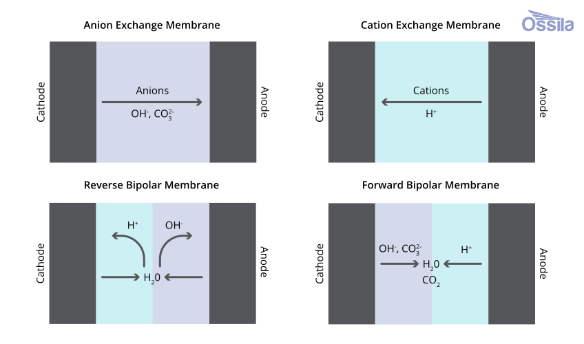
PEMs are a subtype of CEMs. Whereas CEM is the general name for a membrane that allows the passage of cations, PEMs transport H+ from anode to cathode. This creates an acidic cathode environment that strongly accelerates HER, suppressing CO2RR Faradaic efficiencie to single digit values for CO on standard catalysts.
The exception is formic acid production, where acid-tolerant bismuth catalysts in CEM cells achieve CO2RR Faradaic efficiencies above 95% at 400 mA/cm2, with formic acid recovered directly, rather than as a formate salt requiring downstream separation.
CO2 crossover is also suppressed in CEM systems, as carbonate ions cannot migrate through a proton-selective membrane, preserving single-pass CO2 conversion efficiency.
Anion Exchange Membranes
AEM is the current standard for most CO2RR targets. AEM-based electrolyzers selectively transport anions, supporting high Faradaic efficiencies (>90% for CO, >60% for C2+ in alkaline conditions) and alkaline cathode conditions compatible with Cu, Ag, and Bi catalyst families.
The central weakness for these membranes is carbonate crossover: CO2 reacts with cathode generated OH⁻ to form bicarbonate and carbonate ions that migrate to the anode, where they are released as CO2 mixed with O2, which gets permanently lost from the system. Carbonate accumulation within the membrane progressively replaces functional OH⁻, reducing ion exchange capacity irreversibly. Long-term AEM degradation under alkaline conditions, particularly hydroxide attack on quaternary ammonium cationic groups remains an active materials challenge.
Bipolar Membranes
Biopolar membranes (BPMs) consist of a cation exchange layer bonded to an anion exchange layer, operable in two orientations. In reverse-bias configuration, water dissociates at the CEL/AEL interface into H+ (migrating to cathode) and OH- (to anode), theoretically preventing ion crossover and maintaining a stable pH gradient. BPMs can enable non-precious-metal anodes by maintaining alkaline anode conditions and can suppress carbonate crossover more effectively than AEM alone. However, practical reverse-bias BPM systems fall below 100% water dissociation efficiency, causing unwanted co-ion crossover that gradually acidifies the anolyte and corrodes nickel-based anodes. Forward-bias BPM avoids some of these voltage penalties and addresses both crossover and salt precipitation in zero-gap configurations but introduces trade-offs in cathode humidification and selectivity that remain under active investigation.
Membrane Selection for CO2RR
| Parameter | CEM/ PEM | AEM | BPM (Reverse Bias) | BPM (Forward Bias) |
|---|---|---|---|---|
| Ion Transported | H+ (proton) | OH-, HCO3-, CO32- | H+ (to cathode) / OH- (to anode) | OH- / H+ - water recombination |
| Current Density | Up to ~100 mA/cm2 | 100–500 mA/cm2 | >200 mA/cm2 to 1 A/cm2+ | Up to ~300 mA/cm2 (demonstrated) |
| Cathode pH | Acidic - promotes HER | Alkaline - suppresses HER | Acidic/tunable, low HER if catalyst correct | Alkaline - compatible with most CO2RR catalysts |
| Anode pH | Acidic | Alkaline / neutral | Alkaline | Acidic |
| CO₂ Crossover | Low, carbonate blocked by H+ selectivity | High, carbonate migrates to anode, lost as CO2 | Very low, BPM blocks ion crossover theoretically | Low, reduced vs AEM but some crossover observed |
| Single-pass CO2 Utilization | High, no carbonate loss | Low, 40–60% typical; carbonate crossover dominant | High, up to 96% demonstrated | Moderate, better than AEM, some crossover remains |
| Faradaic Efficiency | Low for most products. Exception: formate >95% with acid-tolerant Bi. | High. >90% CO/formate. >60% C2+ in alkaline. | Lower than AEM currently. | Moderate, humidification-sensitive, CO selectivity declines >100 mA/cm2 |
| Cell Voltage / Energy | Moderate, low resistance but large HER overpotential | Good, low resistance, alkaline OER kinetics | Higher, water dissociation adds ~0.83 V penalty | Lower penalty than reverse-bias, complex water balance |
| Anode Catalyst | Ir/Ru OER required (acid) | Ni, Co-based OER compatible (alkaline) | Ni, Co-based in principle, limited by WDE <100% | Ir/Ru OER required (acidic anode) |
| Salt Precipitation Risk | Low in catholyte-free design | High, K+ + HCO3- crystallizes in GDE pores | Low, ion blockade limits cation transport to GDE | Low, addresses precipitation vs standard AEM |
| Long-term Stability | Good, PEM mature, limited by catalyst acid corrosion | Moderate, AEM degrades under alkaline; carbonate replaces OH- | Emerging, WDE <100% causes anolyte acidification; Ni corrosion reported | Emerging, water balance sensitive; limited long-term data |
| Recommended Use | Formate/formic acid with acid-tolerant catalysts, high CO2 single-pass conversion | CO, C2+, standard GDE and MEA research, widest product compatibility | High CO2 utilization, non-precious-metal anode, scale-up with carbon accounting | Salt-free operation, zero-gap MEA with CO2 + water feed, avoiding GDE flooding |
Further Resources
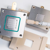 Troubleshooting CO2RR
Practical hardware decisions determine whether a CO2RR electrolyzer operates reliably at elevated current density. These include flow field plate material selection, flow field geometry, and the operational failure modes such as salt precipitation, GDE flooding, membrane degradation, and catalyst contamination that account for most lab-to-scale-up failures.
Read more...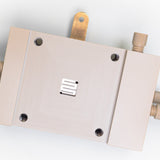 Gas Diffusion Electrodes (GDE)
A gas diffusion electrode (GDE) is a porous, multilayer electrode that facilitates the meeting of a gaseous reactant, a liquid electrolyte, and a solid catalyst at a single, well-defined interface, known as the triple-phase boundary (TPB).
Read more...Contributing Authors
Written by
Product Development Electrochemist
Videography by
Graphic Designer