Five-necked Electrochemical Cell Set up
Captions


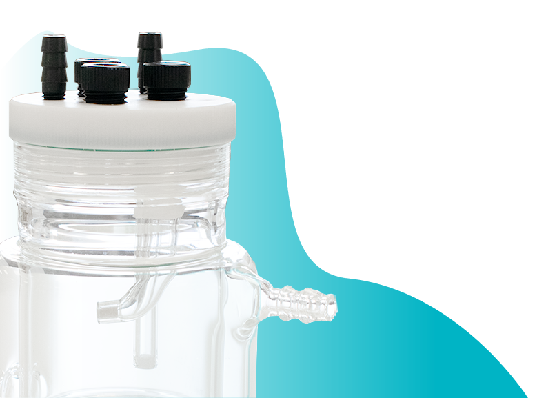
- Five-neck cells are available as a specialised design, with or without a water jacket
- The cell features five ground-glass taper ports: one central port and four side ports
- an F-shaped dual port
- Top port: Bubbling port used to introduce gas into the electrolyte via a submerged tube.
- Blanket port: Directs gas into the headspace above the electrolyte to maintain a positive inert gas atmosphere
- The dual-port design is particularly useful for corrosion studies and when using RDE/RRDE electrodes, where achieving a physical seal can be challenging.
- Water seal: Once filled, it acts as a one-way valve, regulating internal pressure and isolating the system from the external environment
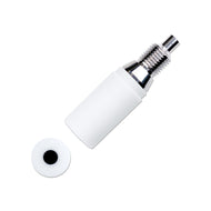
- Use PTFE taper ports to achieve a secure seal around electrodes
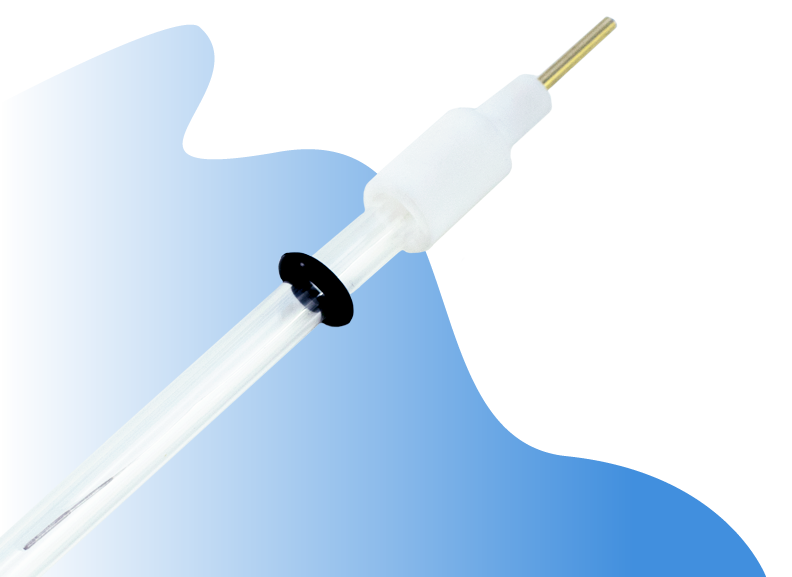
- A Luggin capillary is provided for the reference electrode port
- Next, we’ll demonstrate electrode installation. (Electrodes are not included.)
- Let’s begin with the working electrode
- The port is large enough to accommodate RDE and RRDE electrodes
- Use the blanket port to maintain positive gas pressure where a physical seal is difficult to achieve
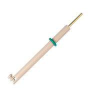
- A user-selected working electrode holder or disk electrode can be used with the cell
- The port provides a secure seal for bespoke electrodes up to 20 mm wide when mounted with a compatible electrode holder
- Follow these steps to achieve a secure seal
- Select an appropriate reference electrode for your system
- The Luggin capillary allows placement of the reference electrode closer to the working electrode
- Note: Fill the salt bridge and allow equilibrium to establish before assembly
- Use the supplied PTFE thread seal to secure the Luggin capillary if required
- Make sure the Luggin Capillary is directed towards the Working Electrode
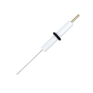
- Let’s now install the counter (auxiliary) electrode
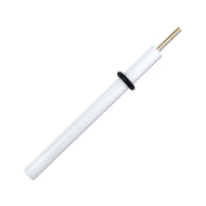
- A platinum wire can be used
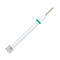
- Alternatively, a coil, plate, mesh, or graphite rod may be used. Here, a reinforced 10 mm × 10 mm platinum mesh is shown
- A range of spare parts is included to support your research are PTFE Tape, Glass Port Covers, Additional FKM fluoroelastomer O-ring, Extra POM electrode securing screws and O-rings, PTFE Electrode Stoppers, Glass Stoppers
- Please refer to the manual for additional information
- For further assistance, contact us via the product page or at support@ossila.com
Compatible with
Related Products

Spectro-electrochemical Cells
Explore our Spectroelectrochemical range, including in-situ Raman Cells.
Electrodes
Explore our range of electrodes, including the glassy carbon working electrode.
Contributing Authors
Written by
Product Development Electrochemist
Videography by
Graphic Designer