Spray Coating: Droplet Formation and Deposition

Spray deposition or spray coating is a scalable wet-coating technique used in many applications. A spray coater can be used in many industries to coat large substrates or objects with odd shapes. The flexibility of the applicator and robustness of the process means that spray coating can be adapted to coat almost anything.
During spray formation, you break a feed of solution into a fine spray of solution particles which is then directed towards the surface you wish to coat. There are different ways to break the solution into a fine spray. Alongside droplet size, how the spray is directed towards a substrate and the drying process impact film quality.
The biggest difference between different spraying processes is exactly how the solution is dispersed into a fine spray of small droplets. Each type of spray coating changes droplet size through a different method, so are often better suited to different solution types. There are, generally speaking, three different ways that this can be done:
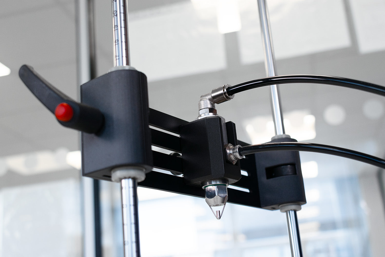
Spray Coater

Air-Assisted Spray Deposition
Air-assisted spray coating, as the name suggests, involves using a gas (normally compressed air) to help form the spray.
- Firstly, the coating solution and the pressurized gas are mixed. This can either be done inside the spray head before the nozzle or outside the spray head just after the solution has exited the nozzle.
- For both processes, a central column of pressurized gas is ejected from the spray coating machine. The solution is mixed into this stream and forms a mixed phase.
- At the interface between the solution and air, there are velocity differences and shearing will take place with the formation of Kelvin-Helmholtz instabilities within the solution. This results in the formation of surface waves, then ligand-like structures which ultimately break off and form droplets.
For air-assisted spray deposition, there is a balance between the shear forces (acting to break up the solution) and the inertial forces (acting to keep the solution together) which ultimately determines the droplet size. The inertial forces are related a solutions viscosity (mu) and surface tension (sigma). The surface tension acts to reduce the surface area of the liquid keeping the solution in a larger droplet, and the viscosity acts as a resistive ‘frictional’ force lessening the impact of shear forces on the solution. Liquids that have high surface tensions such as water-based solutions, and high viscosities tend to form larger droplets.
You can control shear forces by either increasing the density of the gas used, which is generally quite difficult, or by increasing the velocity of the gas. You can increase gas velocity by varying the pressure of the gas being supplied.
There are three dimensionless numbers which can be used to generally assess droplet size for spray atomization. These are the Reynolds number, the Weber number, and the Ohnesorge number.
Where 𝜌 is the density, v is liquid velocity, µ is viscosity, σ is the surface tension for the liquid (l) in question, and d0 is the characteristic length (often the diameter of the nozzle orifice).

The Reynolds number reflects how the inertia of the fluid flow dominates over viscosity. A higher Reynolds number will result in more turbulent flow and more breakup of the liquid. More viscous solutions have a lower Reynold number.

Where vΔ is the relative velocity between the liquid and gas, 𝜌g is the gas density and σ is the surface tension for the liquid (l). The Weber number reflects how the shear forces of the carrier gas-liquid mixture dominate over the surface tension. Higher Weber number means that the system will tend towards liquid breakdown. Solutions with high surface tension will have lower Weber number, so will be harder to break down.

The Ohnesorge number is the ratio of the Weber number and the Reynolds number, and represents the level of viscous dampening of the fluid breakdown. Lower Ohnesorge numbers mean the atomization of the fluid is less hindered by the viscosity of the liquid.
Internal vs External Mixing
As mentioned, there are two different nozzle designs for air-assisted spray coating, an internally mixed version and an externally mixed version.
The most commonly used system is the internally mixed head. This one involves mixing solution and liquid inside the head. There is a small chamber inside the spray head where pressurized air is fed in. There is also an opening towards a fluid reservoir. The movement of air out of the nozzle siphons fluid out of the reservoir, drawing it into the mixing chamber. Here it is mixed into the gas stream exiting the nozzle. Atomization occurs after the liquid-gas mixture exits the nozzle.

An external mixing head on the other hand has the air nozzle and liquid nozzles separate from one another. The solution is forced out of the spray head nozzle under pressure causing forming a small jet of fluid. This fluid jet is directed towards a jet of gas that itself is directed towards the surface that is to be coated. In this setup mixing and atomization occur simultaneously.

The equations used to describe the Reynolds number previously work well for external mix systems. However, when it comes to internally mixed systems this becomes more complex. The Reynolds number outlined earlier is appropriate for describing the liquid entering the mixing chamber, but not for the gas liquid mixture that leaves the nozzle. Instead, it is better to look at the momentum ratio between the two phases in the mix which is given by:

For the two different mixing designs, there is also a distinct difference between how much liquid can be delivered and how this is controlled. In an external mixing head, an external pressure gradient is used to drive liquid out of the nozzle, this can be controlled by the user independently of any of the gas parameters.
However, for the internally mixed heads, liquids enter the mixing chamber due to a Venturi-driven siphoning effect. This results in the amount of liquid being delivered being correlated to the pressure of the gas used. So, it is impossible to decouple droplet size from the liquid flow rate.
Hydraulic Spray Deposition
If we take the externally mixed head and look at an extreme version of this, we can get a hydraulic spray coating nozzle. Here no gas is used to atomize the liquid, and the atomization process is solely due to the shearing of liquids leaving the nozzle. These are often referred to as airless spray coating systems.
The pressures used to drive the liquid through the nozzle are significant and can be in the region of 100 bar to 250 bar. In this situation the atomization of the liquid is not due to Kelvin-Helmholtz instabilities and shear driven breakdown, but instead are solely due to turbulent breakup of the liquid.
For hydraulic spray coating equipment, the Weber number is not indicative of droplet sizes. It can only tell you if atomization will occur. Instead, we can look at the Reynolds number alone to see how the degree of atomization will change. With a higher Reynolds number, the fluid experiences a higher degree of turbulence resulting in a greater breakdown of the fluid. So, the droplet size is determined only by the nozzle geometry, and the fluids viscosity, surface tension and velocity.
Just like the internally mixed head for the air-assisted system, there is a trade-off between atomization and fluid volume delivery. To get smaller droplets higher solution velocities are needed. Often spray systems will operate with fixed nozzle diameter as there is a limit to how small these can go. This once again means that the degree of atomization and the fluid volume and rate cannot be decoupled.
Having said this, there are some airless spray systems which are capable of decoupling spray volume and atomization through smart engineering practices. These operate by pulsing the spraying of the system at high frequencies introducing a duty cycle to the spraying. Users can tune the system to spray between 0% of the time and 100% of the time. By reducing the duty cycle and increasing the pressure of the head you can reduce the droplet size and maintain the same volume flow of solution.
Ultrasonic Spray Casting
The final method of atomization is through ultrasonic vibration on a small tip. Ultrasonic vibrations can be generated in one of two methods, either using a piezoelectric element driven at high frequencies or using a Helmholtz resonator. This method is different to other spray deposition methods in terms of how the breakdown of liquids work.
In ultrasonic spray coating, the Reynolds number, Weber number, and Ohnesorge number have no impact on the formation of droplets and can effectively be ignored. Instead of shear forces or turbulent flow breaking down the solution, standing waves driven by ultrasonic vibrations cause the breakdown of a thin film of liquid sitting on a tip. This occurs when a critical energy is coupled into the wet film allowing for the standing wave energy to be greater than the surface tension of the film resulting in cresting of the peak of the wave. Once that occurs droplets are ejected that are similar dimension to the standing wave.
Piezoelectric driven ultrasonic spray coating systems will use electronic circuits to control the vibration of the tip via piezoelectric materials. Piezoelectric materials will expand or contract under different electrical conditions, and are often used to control the movement of an object over very small distances by varying voltage.
Often the vibrational frequency of the ultrasonic tips depends upon the resonant frequency of the piezoelectric crystal used as this will be the most efficient frequency to drive it at. However, it is still possible to vary to control the degree of atomization by varying frequency - but by moving away from the resonant frequency of the crystal the efficiency of the system will reduce.
Alternatively to piezoelectric-driven systems, the Helmholtz resonator design relies on pressurized air passing over the entrance of a Helmholtz resonator cavity, the shape of which determines the frequency of vibration. Varying the pressure and flow rate of air passing by the opening increases the amplitude of vibration. However, there is no tunability in the frequency.

In Helmhotz-resonator spray deposition systems:
- Tip vibrates with a set frequency. The amplitude of this frequency determines the coupled energy.
- Liquid dispensed over lip, forming wet film
- Standing wave forms on wet film
- More energy coupled into wet film leads to higher crests
- Droplets break off crests of wave
The size of droplets that are formed are approximately given by the below equation which is derived from the wavelength for capillary waves in thin wet films. Here surface tension (𝜎), the density of the fluid (𝜌), and the frequency (f) the tip vibrates at determine the size of the droplet.

The amount of solution that is atomized in a given time is not dependent upon the frequency but is instead dependent upon the feed rate of solution onto the tip. However, there is an upper limit to the feed rate that the system can atomize, and this is dependent upon the amount of acoustic energy that is coupled into the wet film and the degree of viscous dampening.
The viscous dampening and the low energies that can be coupled into the wet film are what produce certain limitations on what can be done with ultrasonic spray coating. Viscous solutions are not viable as the dampening overcomes the rate at which the energy can be coupled into the wet film. High flow rates also result in the system not being able to break down the wet film and results in liquid dripping from the tip rather than being atomized. Typically, ultrasonic systems are limited to mL/min rates while hydraulic and air-assisted systems can deliver fluids at a rate of L/min.
Spray Shaping
After the liquid is atomized, the spray will form a specific pattern. For the air-assisted and hydraulic spraying systems the atomized spray mixed with the pressurized air results in a cone shaped spray, due to the high velocity of the gas and expansion. For ultrasonic spray deposition, there is no carrier gas present meaning the atomized liquid tends to form a diffuse mist around the tip which falls under gravity. Depending upon the application users may wish to alter the shape of the spray to better suit the surface the solution is being applied to. This is done by jet shaping nozzles.

There are several different patterns that can be made via nozzle design, these include full cone convex, full cone flat, hollow cone, flat fan, convex fan, mister, and straight jet.
In addition to the shape of the spray, the nozzles can also be configured in either a direct or deflector arrangement. For direct arangements the spray direction is in line with the initial jet of atomized liquid. Alternatively in deflector arrangements, the spray direction is at a specified angle to the initial jet and deflected downwards. Ultrasonic nozzles are often limited to either fan shapes or straight jet, however some manufacturers do supply other designs such as full cone.
Depending on the nozzle design, the air used for atomization is also used for the spray shaping. Changing the pressure of this spray shaping air inlet can have an effect on spray patterns and dimensions. For example, higher pressures on a flat fan nozzle will result in a thinner wider spray, while for a straight single point it will result in a smaller point size. This can be inconvenient in certain applications as you may want to be able to vary the solution atomization without impacting the spray shape. In these situations, having a nozzle design where you can vary the pressure of the atomizing air inlet from the spray forming air inlet is ideal.
Fluid Delivery
As mentioned previously, different spray coating system designs handle fluid delivery in different ways. The simplest siphon fed spray coating machine has the fluid delivery rates directly correlated with the pressure of the atomizing air inlet. Externally mixed heads will handle fluid delivery differently to the internally mixed syphon heads. Here, the fluid delivery can be controlled similarly to a hydraulic head by keeping the fluid pressurized - although the pressures used in externally mixed heads are significantly lower than the hydraulic heads, typically between 0 and 1.5 bar gauge pressure.
The correlation between pressure and flow rate will be dependent upon nozzle geometry and fluid viscosity. Narrower orifices, and longer paths of flow will reduce the flow rate for a given pressure. Higher solution viscosities will also reduce viscosity. The pressure differentials that are used for pressure-driven fluids are much higher than the pressure differentials that occur in a syphon fed head. Due to this, pressure-driven systems can deliver a much higher flow rate of solution compared to ultrasonic and siphon fed systems.
To overcome this higher flow rate limitation, you can perform duty cycling of the fluid air inlet, like the hydraulic nozzle. Here you use fast response time solenoids to pressurize and depressurize the liquid feed line. With fast enough response time you can reduce the flow to as low as 0.1% of the initial flow rate for the system. Combining a controllable pressure for the liquid feed and duty cycling of the pressure line this can give you flow rates from 0.1ul/s to as high as 10 ml/s.
Technical Support
Learn More
 Thin Film Deposition: Comparing Coating Methods
Spray deposition or spray coating is a wet-coating technique used in many applications. It is a scalable technique and is used in many industries to coat large substrates or objects with odd shapes. The flexibility of the applicator and robustness of the process means that spray coating can be adapted to coat almost anything.
Read more... Spray Coater: Working Principles and Uses
Spray coaters are versatile and can be used to coat large area substrates with relative ease. These techniques are regularly and reliably used in industry for protective, aesthetic and functional coatings.
Read more...