Organic Light Emitting Diode: OLED Generations & Structure
An organic light emitting diode is a type of light emitting diode (LED) which using organic materials as the emissive layer. LEDs convert electrical energy into light energy via electroluminescence, and they do this very efficiently. By varying the type of OLED materials used, you can easily vary the color of emitted light and efficiently optimize the efficiency and stability of your organic LED device.
Organic light emitting diodes (OLEDs) have been quickly adapted into many display technologies, due to their high contrast ratio, relatively low production costs, and the versatile range of viable organic materials. There has been a lot of interest in industrial and research applications to optimize and improve OLED devices. OLED research and development requires precise and reliable device characterization, using tools like the Ossila LED measurement system.
What are OLEDs?
Organic light emitting diodes are thin film devices that convert electrical energy into visible light. In OLED devices, electrons and holes are injected into the organic medium and recombine radiatively via electroluminescence (EL). The color of the light emitted is dependent on the molecular structure of the organic materials in the emissive layer.
OLED materials can be easily customized to emit a wide range of wavelengths thanks to the endless configurations of organic semiconducting molecules. All OLED materials play a role in charge transport and/or light emission via radiative recombination.
Three forms of radiative recombination are used in different OLED technology:
- Fluorescence
- Phosphorescence
- Thermally-activated delayed fluorescence (TADF)
These three mechanisms define the first three generations of OLEDs (first, second, and third, respectively). Fluorescence only occurs from singlet-singlet transitions and requires the simplest energy transfer pathway. However, these have a limited efficiencies as only 25% of the electron-hole pairs can generate light. Phosphorescence and TADF use both triplet electrons, so second and third generation OLEDs can achieve higher efficiencies.
The Generations of OLED emitters
There are four "generations" of organic light emitting diode defined by their primary radiative recombination mechanism. Different OLED materials are used in each generation.

First Generation OLED (Fluorescent)
First-generation fluorescent emitters can only support radiative emission through singlet-singlet emissions. This limits their efficiency to 25%. These emitter materials tend to be organic dyes such as pyrroline. Although these materials are generally low cost and stable, their limited efficiency is an unavoidable issue.
-
Green Emitters
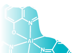
Alq3 was one of the first emitters to create a green emission OLED. These devices achieved 1% EQE and emitted light between 500-550 nm.
-
Red Emitters
The first red fluorescence emitters were created in 1989, created using the dopant 4-(dicyanomethylene)-2-methyl-6-[4(dimethylaminostyryl)-4H-pyran] (DCM). However, increased concentration of this dopant causes aggregation, which completely quenches any emission. First generation OLEDs also include DCM-based dopants (such as DCJTB) are still used in fluorescent OLEDs.
Second Generation OLED (Phosphorescent)
Second generation OLEDs use phosphorescence as their main light emitting mechanism. These utilize delayed photoluminescence, through the forbidden triplet-singlet emissions. As they utilize triplet state electrons, photoluminescent materials have a theoretical efficiency much higher than fluorescent based OLEDs. These are much more commonly used in OLED devices and technology. PhOLEDs (phosphorescent OLEDs) usually involve heavy-metals atom such as iridium and platinum. This can be an issue as the utilization of heavy metals can pose environmental and cost concerns.
-
Green Emitters
Ir(III)-based materials (like Ir(ppy)3 and Ir(ppy)2acac are often used in PhOLEDs for green emission. This is because they are highly efficient and very stable. Ir(III)-based emitters can also use different functional ligands to acheive color switchable OLEDs. Ir(ppy)3 is a relible high quality PhOLED material. Other PhOLEDs use Pt-based materials and other heavy metals.
-
Orange-Red Emitters
Finding a high efficiency orange-red PhOLED material is more tricky. Possible candidates are iridium and platinum complexes similar to those used for green emitters. These can include materials such as Ir(piq)3 and Ir(piq)2(acac).
-
Blue Emitters
Iridium and platinum complexes could also be used to create blue emitters. Sky blue emitters have been created using phosphorescent materials. However, the challenge lies in producing a deep blue. Both modified iridium and platinum complexes have demonstrated some ability to create blue emitters.
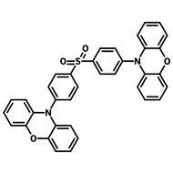
Phosphorescent Emitters


Third Generation OLED (TADF)
The third generation of OLED devices use thermally activated delayed fluorescence. In this process, triple electrons can be converted into singlet electrons, which can then decay through the allowed singlet-singlet transitions. This means a material can utilize both triplet and singlet electrons, increasing theoretical efficiency to 100%.This makes TADF materials a very promising area of research.
-
Green Emitters
The use of TADF emitters in OLEDs was demonstrated in 2011 using PIC-TRZ. In 2012, devices using 4CzIPN, a carbazole-based donor-acceptor compound, demonstrated EQEs over 19%, smashing any fluorescence emitter performance. Since then a wide range of TADF materials have been used for green OLEDs. These include CzDBA, 2F-BN, 4CzTPN, and PXZ-DPS.
-
Orange-Red Emitters
In 2012, orange-red OLEDs achieved an EQE of 11.9% at 580 nm using 4CzIPN-Ph. Deep red OLEDs (emission at 688 nm) were created in 2015 using TPA-DCPP. Considerable efforts were made to improve device performance and durability by incorporating various exciplex formation strategies. By 2019, deep red TADF OLEDs had achieved impressive EQEs exceeding 30%, with the potential for emission wavelengths extending into the infrared. However, producing red TADF OLEDs remains a challenging task with relatively few positive results compared to the other TADF emitters.
-
Blue Emitters
Blue TADF OLEDs face challenges related to their lifespan and material degradation due to the high energies involved. In 2012, notable progress was made with deep blue TADF emitters, such as DTC-DPS, which had promising characteristics. A "sky blue" emitter called 2CzPn also emerged that year. In 2014, the TADF technology produced competitive blue emitters like DMAC-DPS and DMAC-TRZ. Since then, many more blue TADF emitters are being explored in this field.
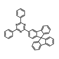
TADF Emitters


Fourth Generation OLED (Hyperfluorescence)
Hyperfluorescent OLEDs (HF-OLEDs) represent the fourth generation of OLED technology. They combine thermally activated delayed fluorescence (TADF) with traditional fluorescence to achieve highly efficient, narrowband emission.
In HF-OLEDs, triplet exciton harvesting is enabled through a TADF sensitizer via reverse intersystem crossing, while Förster resonance energy transfer moves these excitons to a fluorescent emitter. This mechanism allows the system to theoretically harvest all excitons and emit them as highly efficient, narrowband fluorescent light.
The emissive layers of HF-OLEDs consist of three components: a host, a TADF sensitizer, and a terminal emitter. The components are discussed below in relation to their roles in different types of color emission.
-
Green Emission
Green HF-OLED devices offer high color purity and high efficiency. Optimized energy gaps between the TADF sensitizers and final fluorescent emitters are crucial to improve the performance and reduce EQE roll-off of the devices. Some key TADF sensitizers to be used are 4CzIPN, 4CzTPN and PXZ-DPS. Common fluorescent dopants include tetracoordinate boron-dipyrromethene (BODIPY) derivatives such as tPhBODIPY.
-
Orange-Red Emission
Metal-free red emitters are rarely reported. The fluorescent emitter DBP is commonly used in HF-OLED systems with efficiencies of 16.9 % with the TADF sensitizer TXO-TPA and 15.9 % with the sensitizer 2,7-TXO-PhCz. The red BODIPY based dopant, 4tBuMB has been used in a HF-OLED device alongside 4CzTPN, achieving an EQE of 19.4 %. Further development of highly efficient organic-based red devices is still in progress.
-
Blue Emission
The first blue HF-OLED device combined ACRSA as the TADF sensitizer and TBPe as the fluorescent emitter achieving efficiency of 13.1%. Since then, molecular engineering has seen efficiencies soar. Wide band gap hosts with a high triplet state, such as DPEPO, also increase device efficiency. TADF sensitizers with rapid RISC rates through donor/acceptor unit design and a small energy gap between the singlet and triplet states.
Doped fluorescent emitters such as DNTBPe achieve increased emission efficiency. New emitters for final dopants have also emerged to contribute to the HF system. The main requirements are:
- A narrow blue emission spectrum with a wavelength range of 440–470 nm
- A small Stokes' shift
- A large spectral overlap with TADF emission.
Hyperfluorescence Materials


OLED Device Structure

OLED devices require multiple different layers including:
- The supporting substrate
- The cathode
- The organic emissive layer
- The anode
For example, in the image here you can see that the organic emissive layer is sandwiched between two conductive layers: the ITO anode and an aluminum cathode. The whole device is constructed on a transparent glass substrate.
When choosing your emission layers and contacts, there are several things you must consider:
- Emissive Layer - The emissive layer is where the holes and electrons recombine radiatively. Ambipolar materials (that can transport both electrons and holes) are usually used as OLED emissive layers. With ambipolar materials, distribution of hole and electrons will be uniform throughout the layer, leading to even charge balances. This results in higher efficiencies.
- Anode and Cathode - The anode and cathode are the metallic contacts that apply a voltage over the device. Usually one of the contacts is transparent to allow light emission. There must be good energy level alignments at the anode/organic and cathode/organic interfaces to ensure good electron injection and extraction into the emissive layer. You can also employ electron and hole injection layers to improve this process.
Additionally, there are several layers which can be used in organic light emitting diode devices to control and improve charge transport through the device. Some examples of these layers are listed below.
- Hole injection layer (HIL) and electron injection layer (EIL) - These are organic layers that help with hole and electron injection, located next to the anode and cathode. The HOMO (highest occupied molecular orbit) of the HIL and the LUMO (lowest occupied molecular orbit) of the EIL are usually comparable to the next layers HOMO and LUMO to prevent a large energy step that opposes the flow of charge. The HIL and EIL are very thin layers and can be less than 5 nm thick.
- Hole transport layer (HTL) and electron transport layer (ETL) - Similar to the HIL and EIL, the HTL and ETL are organic and have similar energy level positioning to allow favorable charge flow. These layers are selected to have good charge mobility and are usually doped to improve conductivity. Unlike the HIL and EIL, they are much thicker (>10 nm). This is mainly to help thicken the device to reduce the chance of shorting.
- Hole blocking layer (HBL) and electron blocking layer (EBL) - As the efficiency of the device is dependent on how many holes radiatively recombine with electrons, confining the charges in the emissive layer is important. This is where the HBL and EBL come in. The HBL allows electrons to pass into the emissive layer and confines holes in this layer. This is achieved by the HBL having a similar LUMO to the emissive layer and ETL, and a HOMO that is lower than the emissive layer. The EBL does the same but allows holes to pass and confines electrons with a higher LUMO energy level. This prevents exciton quenching.

OLED Hosts and OLED Dopants
Some emissive layers use a host-dopant system (also known as a host-guest system). In this arrangement, the bulk of the emissive layer consists of the host material, and small amounts of the dopant material is dispersed within it. The HOMO and LUMO of the host material align with corresponding transport layers, facilitating charge carrier transport into the EML. Excitons formed on the host molecules are then transferred to the dopant molecules which have a slightly smaller band gap. On the dopant molecules, the excitons radiatively recombine, emitting a photon with a wavelength equal to the band gap.
Host-dopant emissive layers are used in phosphorescent or TADF based OLEDs. These systems can theoretically achieve 100% internal quantum efficiency by harvesting both singlet and triplet excitons. OLED host materials play a very important role in managing charge injection and transportation, reduces non-radiative recombination, and can improve the stability of devices. Meanwhile, the OLED dopant materials will determine the wavelength and efficiency of the radiative emission.
OLED Materials
OLED materials can be split into two broad categories depending on their material type. These are polymer (PLEDs) and small molecules.

Small Molecule OLEDs
The term OLED typically refers to small molecule organic light emitting devices. Here, small molecules are modified to change their material properties, allowing luminescence in the desired wavelength. Small molecule OLEDs often require complex device design. These materials can be further categorized into fluorescent vs. phosphorescent or single-component type vs. host-guest type.
Small Molecule OLED Materials By Role

Charge Transport Layer Materials
Charge Transport Layer Materials
Explore our range of charge transport layer materials.
Polymer OLEDs
Polymer-based OLEDs (PLEDs) are made using an electroluminescent polymers. These must be solution processed, and material properties can be altered by side chain substitution. There are two main subtypes of PLED.
Conjugated Polymers
These include materials like PPV, PF, and PPP. They feature delocalized pi-electron systems. Conjugated polymer systems do not requiring complex device structures. They contain functional units with wide bandgap backbone units, electron and hole affinity units, or emissive units, making them suitable for cost-effective mass production.
Non-Conjugated Polymers
These include materials like PVCz (used as a host material) and are often employed for the fundamental study of OLED properties. Non-conjugated polymers provide substantial control over emissive and carrier-transporting functions and can be customized using different functional units. They can further be divided into:
- Pendant-type, where functional units attach to a non-conjugated backbone.
- Host-guest type, where functional materials (guests) are doped into non-conjugated materials, potentially incorporating fluorescence or phosphorescent emitters.
Dendrimer Materials
Dendrimers act as intermediaries between small molecules and polymers in OLEDs. They are often used in combination with polymers to enhance performance. Dendritic compounds with iridium complex cores have also created phosphorescent materials that emit in various colors.
Why are OLEDs Successful?
In recent years, OLEDs have been adapted into a wide variety of display technologies due to their impressive light generation efficiencies. We can see this in the widespread use of OLEDs in portable displays, laptops, tablets, and smartphones. OLED televisions are very attractive prospects as they have excellent emission colors, a high on/off contrast ratio, and wide viewing angle - the latter of these factors is still challenging for conventional LED televisions.
For these reasons, organic light emitting diodes are becoming increasingly popular in both research and industry. Since the year 2000, the number of research papers published about or surrounding OLEDs has steadily risen. Each year, there are about 1500 to 2000 new papers published surrounding OLED research. Plus, there's a noticeable increase in patents filed related to OLEDs. This shows that there is a rapidly growing market for OLEDs. Market analysis suggests that by 2030, the value of the OLED market could reach 214.8 billion USD.


The reasons for the rise in OLED popularity is that they demonstrate many improved properties compared to their LED counterparts:
- Wide emission angles
- High purity of color and able to produce a "true black"
- Fast response times
- High efficiencies
- Wide range of possible emission wavelengths and color temperatures (1500-20000 K)
- High tolerances for bending and twisting, so can be fabricated on a wide range of substrates.
One of the most promising advantages of OLEDs is their mechanical flexibility. This has also allowed the development of flexible and curved displays. Both offer novel device architectures for smartphones where screen size has previously been sacrificed for portability. As for televisions, the ability to curve the screen offers an improved field of view that improves the viewing experience.
What Issues Do OLEDs Face?
There are still some challenges of OLED technology:
- Reducing high manufacturing costs of OLED devices
- Improving device stability
- Successfully producing stable, efficient blue and deep-blue OLEDs
Stability Issues
There are several areas of improvement with regards to OLED stability.
Oxygen and Moisture Sensitivity
Many OLED devices are extremely sensitive to oxygen and moisture so most OLED devices have to be made and encapsulated in an inert environment, such as a glove box. This can raise production costs. It also means that OLED encapsulation is extremely important as poor encapsulation can tank device performance.
High Purity Material Needed
Display technology demands long device lifetimes. To acheive this, organic materials in OLED devices need to be of sublime grade but sublimation requires long processes that are not cost effective.
Lifetime vs. Efficiency
You obviously want to create OLEDs that can maintain long lifespans while producing high brightness light. However, generally as the brightness of an OLED increases, the lifetime decreases. One way to achieve longer operational lifetime is to try and achieve high brightness at a low voltage.
Other Stability Issues
Other OLED stability issues include poor interfacial bonding and the migration of metal ions through the device. Additionally, OLED devices need to be robust in strenuous conditions, for example under high temperatures. OLEDs can be prone to temperature degradation leading to malfunction or fracture. In many OLED devices, mechanisms are put in place to dissipate heat, reducing this effect. Prolonged exposure to moisture, or oxygen along with any impurities can also reduce a device’s lifetime, introducing trap states that encourage non-radiative recombination.
Blue OLEDs
It has been especially difficult to develop a stable OLED device which emits blue light strongly. The short lifetime of blue OLEDs are generally attributed to their higher energies, wide band gaps, and long exciton lifetime. Efficient red, green, and sky-blue OLED materials have been created successfully, but research continues to find an efficient and stable blue and deep-blue OLED emitter.
Low Cost Manufacturing
Lots of organic light emitting diodes are deposited by vacuum-processing methods such as thermal-evaporation or e-beam coating. This produces high quality OLED devices but is very expensive. It is especially costly if you are considering producing the large area devices that are need uniform light output.
Organic molecules are similar to organic dyes so in theory inexpensive fabrication of OLEDs is possible through solution processing methods. However, this has yet to be achieved. Printed devices would lower manufacturing costs of OLEDs significantly. Solution processibility opens the doors for OLED on a wide range of thin and flexible substrates. Therefore, there is much drive within the OLED community to develop an efficient, stable OLED device that can be made by solution processing methods.
OLED Materials
Read More...
 Introduction to Phosphorescent Organic Light-Emitting Diodes
In PhOLEDs, charge carriers are injected from the electrodes into the organic layers, where they recombine in the emissive layer to radiatively emit phosphorescence. Find out more.
Read more... Hyperfluorescence: The Next Generation of OLED
Hyperfluorescence organic light-emitting diodes (HF-OLEDs) represent the 4th generation of OLED technology. Find out more.
Read more...Contributing Authors
Written by
PhD Student Collaborator
Reviewed and edited by
Application Scientist
Edited by
Application Scientist
References
- Sekine, C. et al. (2014) ‘Recent progress of high performance polymer OLED and OPV materials for organic printed electronics’, Science and Technology of Advanced Materials, 15(3), p. 034203. doi:10.1088/1468-6996/15/3/034203.
- Hong, G. et al. (2021) ‘A brief history of OLEDs—emitter development and Industry Milestones’, Advanced Materials, 33(9), p. 2005630. doi:10.1002/adma.202005630.