Making Perovskite Solar Cells with I101 Perovskite Precursor Ink

This guide describes our recommended fabrication routine for perovskite solar cells using Ossila I101 Perovskite Precursor Ink can be used in many different device architectures. Here, we show an example of a standard architecture device and an inverted architecture device using I101 perovskite precursor ink.
- Standard Architecture: FTO / TiO2 (Compact) /TiO2 (Mesoporous) /I101 / Spiro-OMeTAD/ Au
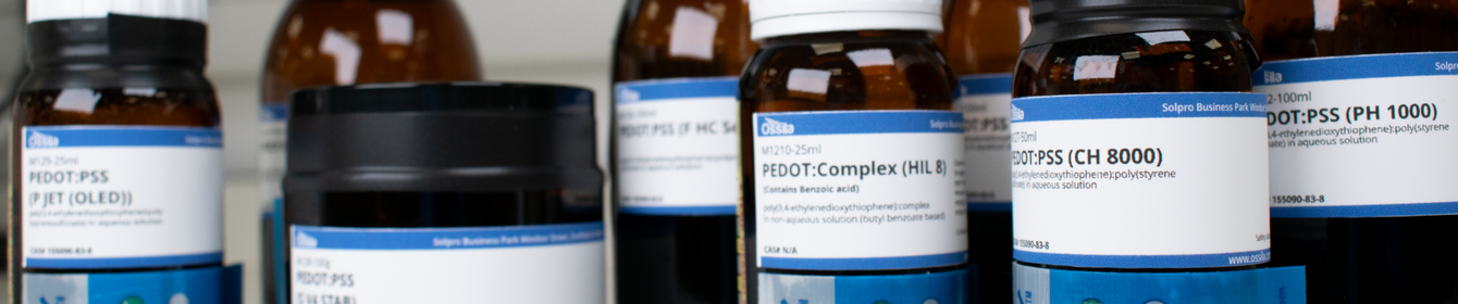
- Inverted Architecture: ITO / AI 4083 PEDOT:PSS / CH3NH3PbI3-xClx / PC70BM / Ca / Al
A complete description of our process routine is shown below. You can also download a one page condensed version for use in clean rooms.
We have also produced a full length video guide for this fabrication routine which includes each step, including substrate cleaning, encapsulation and testing of the devices.
Should you have any queries or technical questions about this perovskite fabrication routine please contact us and we'll be happy to help.
Equipment Required
Process chemicals and consumables required
- Hellmanex III
- Pixelated cathode pre-patterned ITO substrates
- AI 4083
- 0.45 µm PES and 0.45 μm PTFE (hydrophobic) filters
- Perovskite precursor ink
- Rubber-free syringes
- Micro-precision cleaning swab
- PC70BM
- Chlorobenzene
- Isopropyl alcohol
- Hot water
- Encapsulation epoxy
- Glass coverslips
- Micropipette Tips
Processing equipment required/used
- Polypropylene cleaning beaker
- Substrate rack
- Hot-plate held at 70°C for solutions
- Hot plate held at 90°C for substrates
- Spin Coater
- Ultra-sonic bath
- Laminar flow hood
- Glass-beaker for Hellmanex solution
- Tweezers
- Compressed nitrogen gun to dry substrates
- Glove box containing spin-coater and thermal evaporator
- Pixelated cathode mask
- Solar Cell I-V Test System
- Solar Simulator
- Measurement aperture mask
- Variable volume micropipette
Before beginning device fabrication, it’s best to weigh out all solutions, dopants, and precursors ahead of time using a calibrated microbalance. Even minor deviations in measurements can impact the stoichiometry, which in turn affects device performance. Additionally, we advise against preparing less than 1 ml of any material, as smaller quantities may lead to inaccuracies that can result in uneven layers or inconsistent outcomes.
Fabrication Process
Standard Architecture:
FTO/TiO2(Compact)/TiO2(Mesoporous)/I101/Spiro-OMeTAD/Au
Below is a condensed summary of our fabrication routine for standard architecture devices using our I101 ink.
- FTO etching:
- A complete guide to FTO etching can be found on our FTO product page along with an instructional video
- Substrate cleaning:
- Sonicate FTO for 5 minutes in hot (70 °C) DI water with the addition of 1% Hellmanex
- Dump-rinse twice in boiling DI water
- Sonicate FTO for 5 minutes in Isopropyl alcohol
- Dump-rinse twice in boiling DI water
- Dry FTO using filtered compressed gas
- Place the FTO into the UV Ozone Cleaner and leave for 10 minutes
- Compact TiO2 deposition:
- Prepare a solution of titanium diisopropoxide bis(acetylacetonate) at a volumetric percentage of 8% in isopropyl alcohol (approximately 20 ml will be needed)
- Mask off the substrates such that only the active area of the devices are exposed
- Place the substrates onto a hotplate set to 450 °C
- Using a nitrogen/compressed air gun set it to a pressure of 16 – 18 psi and spray the solution onto the substrates. Leave the solution for 30 seconds to dry, and sinter and repeat the spray process again. Repeat this until you get approximately 40 nm of film, this should take around 10 sprays
- Cover the substrates loosely with foil and leave to sinter for 30 minutes
- After sintering remove the substrates from the hotplate, care should be taken as rapid cooling can shatter the substrate
- Mesoporous TiO2 deposition:
- Using a mesoporous paste with a particle size of 18 nm and pore size of 30nm, prepare a mesoporous film of approximately 200 nm thick
- Place the substrates back on the hotplate, loosely cover with foil and sinter the substrates at 450 °C for 1 hour
- After sintering remove the substrates from the hotplate, care should be taken as rapid cooling can shatter the substrate
- Perovskite deposition (in air):
- Heat I101 ink for at least 2 hours at 70 °C to allow for complete redissolution of solutes
- Allow I101 ink to cool to room temperature before deposition
- Set the hotplate temperature to 90 °C
- Static spin coating: place substrate into spin coater, dispense 30-50 μl and start spinning at 2000 rpm for 30 s
- Place substrate onto the hotplate and anneal for 120 minutes
- After annealing, transfer the substrates into a glove box environment.
- Spiro-OMeTAD deposition (in air):
- Prepare the following solutions; Spiro-OMeTAD at a concentration of 97 mg/ml in chlorobenzene, Li-TFSI at a concentration of 175 mg/ml in acetonitrile, and TBP at a volumetric percentage of 46.6% in acetonitrile
- Combine 1000 μl Spiro-OMeTAD, 30.2 μl Li-TFSI, and 9.7 μl TBP solutions
- Dispense 50 µl of the combined solution onto the perovskite, allowing it to spread across the substrate
- Spin at 2000 rpm for 30 seconds
- Use a high-precision mirco cleaning swab soaked in chlorobenzene to wipe the cathode strip clean
- Spiro-OMeTAD oxidation and anode deposition:
- Place the substrates inside a desiccator in air and leave the substrates for 12 hours in the dark to allow for oxidation of the spiro-OMeTAD film (The amount of time required for complete oxidation of the spiro-OMeTAD may vary depending upon thickness and environmental conditions. Additional oxidation steps may be needed after deposition of anode)
- Using thermal evaporation, deposit an 80 nm layer of gold through a shadow mask to define an active area for your device
- Devices do not need to be encapsulated for measuring performance
- If encapsulation is desired, the spiro-OMeTAD should be allowed to fully oxidize again before substrates are transferred into the glove box and encapsulated
Inverted Architecture:
ITO/PEDOT:PSS AI 4083 /I101/PC70BM/Ca/Al
For a complete step-by-step guide please see our full perovskite solar cells fabrication guide or our instructional video guide below.
Below is a condensed summary of our routine, which is also available to download as a PDF to enable you to print and laminate for use in the clean room.
- Substrate cleaning:
- See substrate cleaning section of standard architecture device guide
- PEDOT:PSS deposition:
- Filter PEDOT:PSS AI 4083 using a 0.45 µm PES filter
- Dispense 35 µl of the filtered PEDOT:PSS solution onto ITO spinning at 6000 rpm for 30 s
- Place substrate onto a hotplate at 120 °C
- After all ITO substrates are coated, reduce the hotplate temperature to 90 °C
- Perovskite deposition (in air):
- Heat I101 ink for at least 2 hours at 70 °C to allow for complete re-dissolution of solutes
- Transfer heated substrate onto spin coater, start spinning at 4000 rpm and dispense 30 μl of I101 ink and leave to spin for 30 s
- Place substrate back onto the hotplate at 90 °C for 120 minutes
- After annealing transfer the substrates into a glove box environment.
- PC70BM deposition (in nitrogen glove box):
- Prepare a solution of PC70BM at 50 mg/ml in chlorobenzene and stir for 3 to 5 hours
- Transfer perovskite-coated substrates into the glove box
- Dispense 20 µl of PC70BM solution onto the spinning substrate at 1000 rpm and spin for 30 s
- Use a micro-precision cleaning swab soaked in chlorobenzene to wipe the cathode strip clean
- Cathode deposition:
- Using thermal evaporation, sequentially deposit 5 nm of calcium and 100 nm of aluminum through a shadow mask to define an active area for your device
- Encapsulate devices using a glass coverslip and encapsulation epoxy
- Expose to UV radiation (350 nm) for ~5 minutes (times vary depending upon source intensity) to set the epoxy
Device performance
We show device characteristics for our best pixel fabricated using our process recipe below in the figure below, using I101 perovskite ink. Devices were tested under a standard AM1.5 solar simulator following a reverse bias sweep. Here, the best performing device had power conversion efficiency (PCE) of 13.7%, a Voc of 0.90 V, a FF of 73% and a Jsc of -20.8 mA/cm2.
| Architecture | Standard | Inverted | ||
|---|---|---|---|---|
| Sweep Direction | Forward | Reverse | Forward | Reverse |
| Power Conversion Efficiency (%) | 13.5 | 13.7 | 12.4 | 13.1 |
| Short Circuit Current (mA.cm-2) | -20.8 | -20.8 | -18.8 | -18.8 |
| Open Circuit Voltage (V) | 0.88 | 0.90 | 0.96 | 0.96 |
| Fill Factor (%) | 73 | 73 | 69 | 72 |


Perovskite Photovoltaic Fabrication Video Guide
For those just beginning their perovskite research, we have produced a video guide demonstrating the entire process of fabricating and measuring perovskite photovoltaics. In our own labs, we have reached efficiencies in excess of 11% using this particular fabrication routine. The video below features an older, discontinued model of the Ossila Spin Coater.
Perovskite Materials
Learn More
 Perovskite Solar Cells Passivation Techniques
Perovskite solar cells have demonstrated impressive device metrics, including open-circuit voltages of up to 1.2V. However, in order for PSCs to achieve their theoretical best efficiencies, all non-essential recombination pathways should be eliminated.
Read more... Methods of Increasing PSC Stability & Durability
This article aims to introduce some methods that have been adapted to improve perovskite solar cell stability.
Read more...
References
- Efficient planar heterojunction mixed-halide perovskite solar cells deposited..., A. T. Barrows et al., Energy & Environmental Science (2014)
- Additive Enhanced Crystallization of Solution-Processed Perovskite for Highly..., P.-W. Liang et al., Advanced Materials (2014)
- The Roles of Alkyl Halide Additives in Enhancing..., C-C Chueh et al, Journal of Material Chemistry A (2014)