Slot Die Coater User Manual

Slot Die Coater

1. Overview
Slot die coating is an advanced thin-film deposition technique that is compatible with large-scale manufacturing processes such as roll-to-roll and sheet-to-sheet deposition systems. The technique is part of a class of coating techniques called ‘metered coating techniques’, in which the thickness of the deposited layers is solely dependent upon the rate of solution flow and the speed at which the substrate moves.
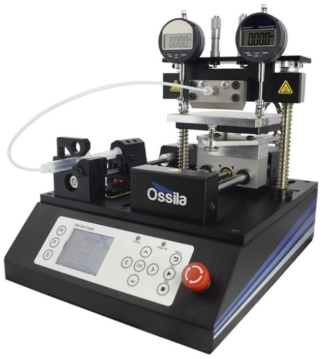
This compact slot die coating system is aimed at research and development teams who are looking to transition away from techniques that are incompatible with large-scale processing, such as spin coating. The Ossila Slot Die Coating System has been designed for simple operation, easy maintenance, and affordability. An integrated high-precision Syringe Pump allows for accurate and reproducible flow rates, which are essential for controlling thin-film thicknesses.
The substrate stage is levelled using a simple three-point levelling system combined with high-precision digital height gauges. Additionally, the stage incorporates a heating element allowing substrates to be heated up to 120°C.
The slot die head is made from stainless steel, ensuring compatibility with a wide range of chemicals. The internal design of the head uses a simple ‘coat hanger’ manifold to distribute the solution evenly across the coating width, resulting in minimal thickness variation.
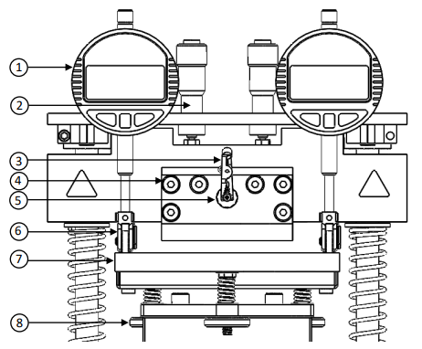
| 1 | Digital Height Gauge |
| 2 | Manual Micrometer |
| 3 | Safety Clip |
| 4 | Slot Die Head |
| 5 | Luer Lock Adapter |
| 6 | Gauge Roller |
| 7 | Heated Stage |
| 8 | Thumb Screw |
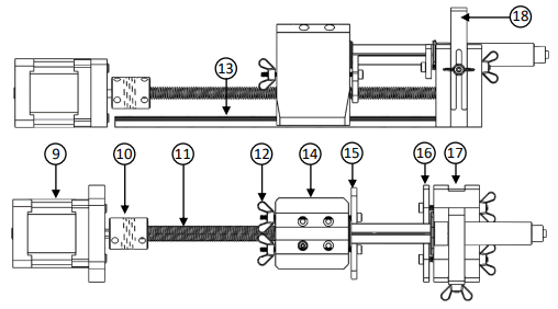
| 9 | Motor |
| 10 | Coupling |
| 11 | Lead Screw |
| 12 | Wing Nut |
| 13 | Rail Guide |
| 14 | Plunger Pusher |
| 15 | Plunger Clip |
| 16 | Flange Clip |
| 17 | Syringe Holder |
| 18 | Barrel Clamp |
2. EU Declaration of Conformity (DoC)
We
Company Name: Ossila BV
Postal Address: Biopartner 3 Building, Galileiweg 8
Postcode: 2333 BD Leiden
Country: The Netherlands
Telephone Number: +31 (0)718 081020
Email Address: info@ossila.com
declare that the DoC is issued under our sole responsibility and belongs to the following product:
Product: Slot Die Coater (L2005A1)
Serial Number: T2005A1 - xxxx
Object of Declaration
Slot Die Coater (L2005A1)
The object of declaration described above is in conformity with the relevant Union harmonization legislation:
Machinery Directive 2006/42/EC
EMC Directive 2014/30/EU
RoHS Directive 2011/65/EU
THe following harmonized standards and technical specifications have been applied:
BS EN ISO 12100:2010 Safety of machinery - General principles for design - Risk assessment and risk reduction
Signed:
Name: Dr James Kingsley
Place: Leiden
Date: 16/11/2021
| Декларация | за съответствие на ЕС |
|---|---|
| Производител | Ossila BV, Biopartner 3 building, Galileiweg 8, 2333 BD Leiden, NL. |
| Декларира с цялата си отговорност, че посоченото оборудване съответства на приложимото законодателство на ЕС за хармонизиране, посочено на предходната(-ите) страница(-и) на настоящия документ. | |
| [Čeština] | Prohlášení o shodě EU |
|---|---|
| Výrobce | Ossila BV, Biopartner 3 building, Galileiweg 8, 2333 BD Leiden, NL. |
| Prohlašujeme na vlastní odpovědnost, že uvedené zařízeni je v souladu s příslušnými harmonizačními předpisy EU uvedenými na předchozích stranách tohoto dokumentu. | |
| [Dansk] | EU-overensstemme lseserklærin g |
|---|---|
| Producent | Ossila BV, Biopartner 3 building, Galileiweg 8, 2333 BD Leiden, NL. |
| Erklærer herved, at vi alene er ansvarlige for, at det nævnte udstyr er i overensstemmelse med den relevante EUharmoniseringslovgivning, der er anført på den/de foregående side(r) i dette dokument. | |
| [Deutsch] | EU-Konformitätserklärung |
|---|---|
| Hersteller | Ossila BV, Biopartner 3 building, Galileiweg 8, 2333 BD Leiden, NL. |
| Wir erklären in alleiniger Verantwortung, dass das aufgeführte Gerät konform mit der relevanten EUHarmonisierungsgesetzgebung auf den vorangegangenen Seiten dieses Dokuments ist. | |
| [Eesti keel] | ELi vastavusavaldus |
|---|---|
| Tootja | Ossila BV, Biopartner 3 building, Galileiweg 8, 2333 BD Leiden, NL. |
| Kinnitame oma ainuvastutusel, et loetletud seadmed on kooskõlas antud dokumendi eelmisel lehelküljel / eelmistel lehekülgedel ära toodud asjaomaste ELi ühtlustamise õigusaktidega. | |
| [Ελληνικά] | Δήλωση πιστότητας ΕΕ |
|---|---|
| Κατασκευαστής | Ossila BV, Biopartner 3 building, Galileiweg 8, 2333 BD Leiden, NL. |
| Δηλώνουμε υπεύθυνα όn ο αναφερόμενος εξοπλισμός συμμορφώνεται με τη σχεnκή νομοθεσία εναρμόνισης της ΕΕ που υπάρχει σnς προηγούμενες σελίδες του παρόντος εγγράφου. | |
| [Español] | Declaración de conformidad UE |
|---|---|
| Fabricante | Ossila BV, Biopartner 3 building, Galileiweg 8, 2333 BD Leiden, NL. |
| Declaramos bajo nuestra única responsabilidad que el siguiente producto se ajusta a la pertinente legislación de armonización de la UE enumerada en las páginas anteriores de este documento. | |
| [Français] | Déclaration de conformité UE |
|---|---|
| Fabricant | Ossila BV, Biopartner 3 building, Galileiweg 8, 2333 BD Leiden, NL. |
| Déclarons sous notre seule responsabilité que le matériel mentionné est conforme à la législation en vigueur de l'UE présentée sur la/les page(s) précédente(s) de ce document. | |
| [Hrvatski] | E.U izjava o sukladnosti |
|---|---|
| Proizvođač | Ossila BV, Biopartner 3 building, Galileiweg 8, 2333 BD Leiden, NL. |
| Izjavljujemo na vlastitu odgovornost da je navedena oprema sukladna s mjerodavnim zakonodavstvom EU-a o usklađivanju koje je navedeno na prethodnoj(nim) stranici(ama) ovoga dokumenta. | |
| [Italiano] | Dichiarazione di conformità UE |
|---|---|
| Produttore | Ossila BV, Biopartner 3 building, Galileiweg 8, 2333 BD Leiden, NL. |
| Si dichiara sotto la propria personale responsabilità che l'apparecchiatura in elenco è conforme alla normativa di armonizzazione UE rilevante indicata nelle pagine precedenti del presente documento. | |
| [Latviešu] | ES atbils tības deklarācija |
|---|---|
| Ražotājs | Ossila BV, Biopartner 3 building, Galileiweg 8, 2333 BD Leiden, NL. |
| Ar pilnu atbilclību paziņojam, ka uzskaitītais aprīkojums atbilst attiecīgajiem ES saskaņošanas tiesību aktiem, kas minēti iepriekšējās šī dokumenta lapās. | |
| [Lietuvių k.] | ES atitikties deklaracija |
|---|---|
| Gamintojas | Ossila BV, Biopartner 3 building, Galileiweg 8, 2333 BD Leiden, NL. |
| atsakingai pareiškia, kad išvardinta įranga atitinka aktualius ES harmonizavimo teisės aktus, nurodytus ankstesniuose šio dokumento | |
| [Magyar] | EU-s megfelelőségi nyilatkozat |
|---|---|
| Gyártó | Ossila BV, Biopartner 3 building, Galileiweg 8, 2333 BD Leiden, NL. |
| Kizárólagos felelösségünk mellett kijelentjük, hogy a felsorolt eszköz megfelel az ezen dokumentum előző oldalán/oldalain található EU-s összehangolt jogszabályok vonatkozó rendelkezéseinek. | |
| [Nederlands] | EU-Conformiteitsverklaring |
|---|---|
| Fabrikant | Ossila BV, Biopartner 3 building, Galileiweg 8, 2333 BD Leiden, NL. |
| Verklaart onder onze uitsluitende verantwoordelijkheid dat de vermelde apparatuur in overeenstemming is met de relevante harmonisatiewetgeving van de EU op de vorige pagina('s) van dit document. | |
| [Norsk] | EU-samsvarserklæ ring |
|---|---|
| Produsent | Ossila BV, Biopartner 3 building, Galileiweg 8, 2333 BD Leiden, NL. |
| Erklærer under vårt eneansvar at utstyret oppført er i overholdelse med relevant EU-harmoniseringslavverk som står på de(n) forrige siden(e) i dette dokumentet. | |
| [Polski] | Deklaracja zgodności Unii Europejskiej |
|---|---|
| Producent | Ossila BV, Biopartner 3 building, Galileiweg 8, 2333 BD Leiden, NL. |
| Oświadczamy na własną odpowiedzialność, że podane urządzenie jest zgodne ze stosownymi przepisami harmonizacyjnymi Unii Europejskiej, które przedstawiono na poprzednich stronach niniejszego dokumentu. | |
| [Por tuguês] | Declaração de Conformidade UE |
|---|---|
| Fabricante | Ossila BV, Biopartner 3 building, Galileiweg 8, 2333 BD Leiden, NL. |
| Declara sob sua exclusiva responsabilidade que o equipamento indicado está em conformidade com a legislação de harmonização relevante da UE mencionada na(s) página(s) anterior(es) deste documento. | |
| [Română] | Declaraţie de conformitate UE |
|---|---|
| Producător | Ossila BV, Biopartner 3 building, Galileiweg 8, 2333 BD Leiden, NL. |
| Declară pe proprie răspundere că echipamentul prezentat este în conformitate cu prevederile legislaţiei UE de armonizare aplicabile prezentate la pagina/paginile anterioare a/ale acestui document. | |
| [Slovensky] | Vyhlásenie o zhode pre EÚ |
|---|---|
| Výrobca | Ossila BV, Biopartner 3 building, Galileiweg 8, 2333 BD Leiden, NL. |
| Na vlastnú zodpovednosť prehlasuje, že uvedené zariadenie je v súlade s príslušnými právnymi predpismi EÚ o harmonizácii uvedenými na predchádzajúcich stranách tohto dokumentu. | |
| [Slovenščina] | Izjava EU o skladnosti |
|---|---|
| Proizvajalec | Ossila BV, Biopartner 3 building, Galileiweg 8, 2333 BD Leiden, NL. |
| s polno odgovornostjo izjavlja, da je navedena oprema skladna z veljavno uskladitveno zakonodajo EU, navedeno na prejšnji strani/prejšnjih straneh tega dokumenta. | |
| [Suomi] | EU-vaatimustenm ukaisuusvakuutus |
|---|---|
| Valmistaja | Ossila BV, Biopartner 3 building, Galileiweg 8, 2333 BD Leiden, NL. |
| Vakuutamme täten olevamme yksin vastuussa siitä, että tässä asiakirjassa luetellut laitteet ovat tämän asiakirjan sivuilla edellisillä sivuilla kuvattujen olennaisten yhdenmukaistamista koskevien EU-säädösten vaatimusten mukaisia. | |
| [Svenska] | EU-försäkran om överensstämmelse |
|---|---|
| Tillverkare | Ossila BV, Biopartner 3 building, Galileiweg 8, 2333 BD Leiden, NL. |
| Vi intygar härmed att den utrustning som förtecknas överensstämmer med relevanta förordningar gällande EUharmonisering som fmns på föregående | |
3. Specifications
The Slot Die Coater specifications are shown in Table 3.1 and Table 3.2.
Table 3.1. Slot Die Coater specifications
| Maximum Hotplate Temperature | 120°C |
|---|---|
| Maximum Travel Length | 100 mm |
| Minimum Stage Speed | 100 μm s-1 |
| Maximum Stage Speed | 50 mm s-1 |
| Minimum Syringe Dispense Rate | 0.021 µL/s for a 1mL syringe |
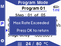
| Maximum Syringe Dispense Rate | 1 mL/s software limit |
| Maximum Substrate Thickness | 13 mm |
| Stage Surface Flatness | <20 μm* |
| Stage Surface Roughness (RMS) | 3 μm* |
| Stage Levelness | <50 μm* |
| Power Supply | Input: 90-264 VAC 50/60Hz Output: 24 VDC, 6.25 A |
| Dimensions |
Width: 280 mm Height: 190 mm Depth: 360 mm |
| Weight | <10kg |
*Values determined at a stage temperature of 21°C.
Table 3.2. Slot Die Coater head specifications
| Slot Die Head Material | Stainless Steel |
|---|---|
| Slot Die Head Coating Width | 50 mm |
| Slot Die Shim Thickness | 100 μm |
| Luer Lock Adapter | Stainless Steel M5 to Luer Lock Adapter |
| Tubing and Connector Material | PTFE Tubing, high density PP Luer lock connectors |
4. Warranty
The Slot Die Coater is covered by Ossila’s two-year warranty. There are no user-serviceable parts in this unit other than the fuse (which is accessible externally). Any modification or alteration may damage the equipment, cause injury, or death. It will also void your equipment’s warranty. If servicing or repair is needed, please contact Ossila to organize a return. Our service department will also quote for any repairs to faults that occur outside the 2-year warranty period.
4.1 What the 2-year Ossila Warranty Includes
- Free return shipping
- Repair, spare parts, and replacement (at Ossila's discretion) of defective products due to faulty materials or workmanship
- If any part is no longer available, Ossila will replace it with a functional replacement part
4.2 What the 2-year Ossila Warranty Does Not Cover
- Normal wear and tear, including parts that might wear out over time
- Damage from external sources such as weather, electrical outages, or power surges
- Equipment that has been modified or serviced by anyone other than an Ossila engineer
- Equipment that has been subjected to chemical damage through improper use
- Equipment that has been operated outside the usage parameters stated in the User Manual associated with the equipment
- Equipment that has been used to process any type of biological materials (viruses, bacteria, bodily fluids, etc.) due to not being able to handle items contaminated with biological waste
- Equipment that has been rendered inoperable through accident, negligence, carelessness, misuse, contamination, improper maintenance, modification, or other external causes
5. Unpacking
5.1 Packing List
The items included in the Slot Die Coating System are:
- Slot Die Coater
- Power supply and power supply cord
- Slot Die Coater Head and connecting screws
- (x5) 25 mm coating width 100 µm thick shims
- (x5) 50 mm coating width 100 µm thick shims
- Luer Lock to M5 thread adapter
- PTFE tubing with Luer Lock adapters
- Tube clip
- (x2) LR44 batteries
- User manual
5.2 Damage Inspection
Upon receiving the unit, examine the components for evidence of shipping damage. If damage has occurred, please contact Ossila directly for further action. The shipping comes with a shock indicator to show if the package has received an impact during transportation.
6. Safety
6.1 Warning
- Only use the 24V power adapter and power cord supplied with the unit.
- If using flammable or hazardous solvents, users are expected to be trained in their usage and carry out a risk assessment.
- Keep the area around the machine clear, 1 m clearance above and 30 cm to the sides.
- Keep clear of the machine while it is in operation.
- If using hazardous solvents always use within a fume hood or controlled environment.
- There are pinch points when in operation, keep hands clear of moving parts.
- Hot plate temperatures can result in severe burns, use caution when operating at elevated temperatures. The LED will blink when the hotplate is heating up and will remain on once it has reached set temperature.
- Do not use in an explosive atmosphere.
6.2 Use of Equipment
This Slot Die Coater is designed to be used as instructed, which is under the following conditions:
- Indoors in a laboratory environment (pollution degree 2).
- Altitudes up to 2000 m.
- Temperatures of 5°C to 40°C; maximum relative humidity of 80% up to 31°C.
The Slot Die Coater is supplied with a 24 V DC / 6.25 A power adapter with a power cord for the country of purchase. This is in accordance with European Commission regulations and British Standards. Use of any other electrical power cables, adapters, or transformers is not recommended.
6.3 Hazard Icons
The following symbols can be found at points throughout the rest of the manual. Note and read each warning before attempting any associated operations associated with it:
Table 6.1 Hazard warning labels used in this manual.
| Symbol | Associated Hazard |
|---|---|
 |
General warning or caution, which accompanying text will explain |
 |
Electrical shock |
 |
Pinch point |
 |
Hot surface |
6.4 General Hazards
When installing or operating the Slot Die Coater, there are several health and safety precautions that must be considered.
WARNING: Improper handling when operating or servicing this equipment can result in serious injury. Pay attention to the following hazards when operating this equipment.

Pinch point and entanglement hazards are present during operation of the syringe pump and stage. As a precaution, users should avoid handling or leaning over the equipment during operation to avoid possible crushing or entanglement of hair and/or clothing. The unit weighs approximately 10 kg. Care should be taken when handling or moving the unit.

In the event of an emergency, the unit can be disabled by disconnecting the power cord from the power supply. Make sure that the power outlet for this cord is readily accessible to the operator.

Servicing should only be performed by an Ossila engineer. Any modification or alteration may damage the equipment, cause injury, or death. It will also void your equipment’s warranty.
6.5 Emergency Stop
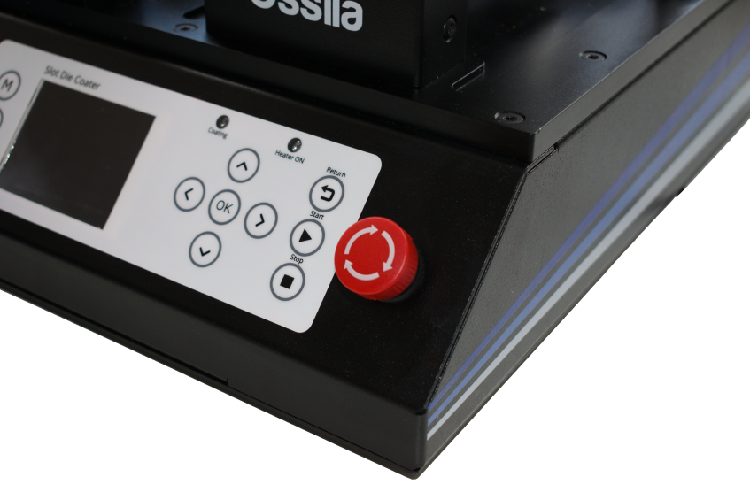
The slot die coater is fitted with an emergency stop button that can be pressed in the event of emergencies e.g. the trapping of objects within pinch points. When pressed, the emergency stop button cuts off the power to the system and a buzzer will turn on to indicate that the button has been pressed. The emergency stop button will remain pressed until the button is rotated clockwise and released. Once released, the system can be restarted by turning the unit off and on again using the on/off switch at the back of the unit. The emergency stop button should not be used for powering down the system after use and should only be used in emergency situations.
6.6 Tube Clip
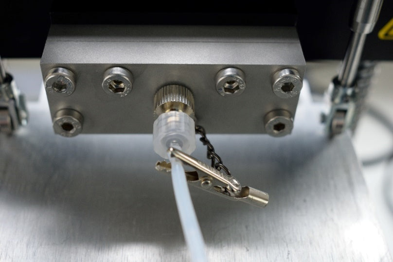
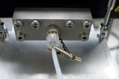
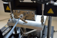
A tube clip has been provided with the system. The clip chain attaches to the slot die head using a simple washer. The clip itself can then be attached to any PTFE tubing that is connected to the system. This ensures that if the polypropylene connector becomes damaged during operation, the tubing is held in place and solution does not escape the system. The clip should be attached whenever the system is used.
6.6 Operational Safety
Any procedure involving the slot die coater should have a suitable operating procedure, risk assessment and COSHH form(s) to ensure that the user is aware of the potential hazards inherent to the work they are undertaking. The following are safety points that should be noted by the user before any procedure is undertaken with the slot die coater.
6.7.1 Pinch Points

Both the syringe pump and the moving stage present the risk of pinch points to the user. It is recommended that any loose articles of clothing and hair are tied back and secured before using the system. In addition, we recommend that users do not place their hands near the moving sections when programs are running or when there is manual movement of the syringe pump or the stage.
6.7.2 Hot Plate

The hot plate can be programmed to reach temperatures as high as 120°C. When the temperature is above 50°C, extreme care should be taken when placing and removing substrates. In addition, risk assessments should consider potential fire hazards that can occur when heating solvents to high temperatures. Many common solvents used within laboratories have a flash point below 120°C, leading to the risk of ignition. Adjust experimental parameters to reduce risk of solvent combustion.
6.7.3 Sources of Ignition

Solvents can often be heated beyond their flash point, where any source of ignition can ignite the solvent. To minimize this risk users should ensure that no sources of ignition are placed close to the slot die coating system.
6.7.4 Fire Hazard

In the unlikely situation where solvents on the hotplate have ignited, the system is designed to contain any solvents either on the hotplate itself or on the baseplate below. This is to stop the spread of fire. Users are also recommended to leave at least 30 cm of space surrounding the entire system, and 1 m above the system, free from any other objects to reduce the possibility of the fire spreading.
7. Maintenance
7.1 Cleaning
Maintenance consists of periodic cleaning. The exterior of the instrument can be wiped with a clean, dry cloth to remove any oil, grease or dirt. Small amounts of solvent can be used to clean the stage and head once it has cooled to room temperature.
7.2 Repair and Service
Periodically, the rail guide and the lead screw should be lubricated with synthetic grease or oil to ensure smooth motion. Repairs or servicing not covered in this manual should not be performed. Contact Ossila if you have issues with your system.
8. Installation
The following procedure should be followed when setting up the unit for the first time.
- Place the unit on a solid, level surface. If necessary, the feet can be rotated to adjust their height and level the unit. Ensure the area is free from vibrations, temperature extremes and highly flammable or explosive materials. Keep the area surrounding the machine clear, with approximately 1 m clearance above the machine and around 30 cm clearance on the sides.
- Remove the cable ties that secure the gantry during shipping.
- Before plugging in the Slot Die Coater, ensure the power switch on the unit is switched to the ‘0’ position (off).
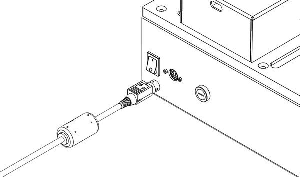
- Connect the power supply connector to the Slot Die Coater (shown in Figure 8.1).
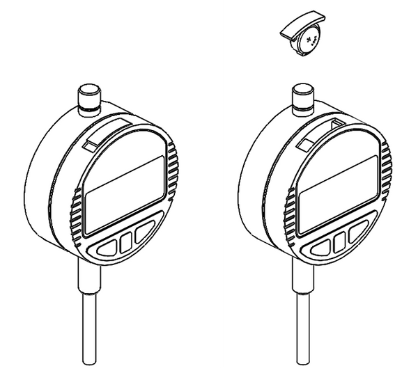
- Insert one LR44 battery into each digital height gauge by removing the cap (shown in Figure 8.2).
- You may wish to turn the digital height gauges off when not in use to conserve battery life. This is done by pressing the ‘OFF/ON’ button. The digital height gauges are not powered or charged by the mains supply.
9. Operating the Slot Die Coater
9.1 Slot Die Coater User Interface
The control panel of the Slot Die Coater is shown in Figure 9.1. It consists of an LCD display, 11 control buttons and 2 indicators. The functions of the buttons are described in Table 9.1.
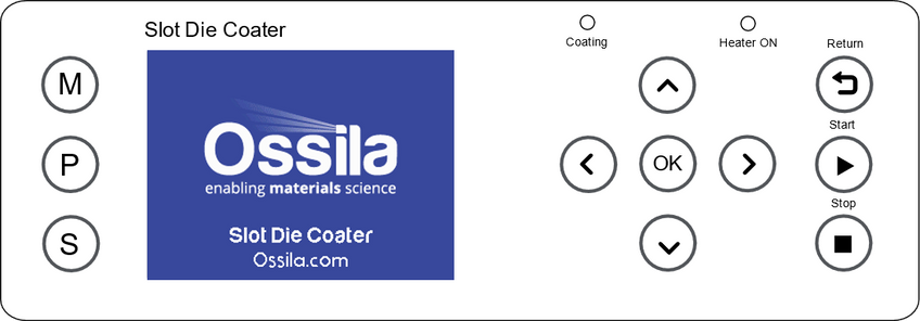
Table 9.1. Operational buttons and their associated functions
| Button | Name | Function |
|---|---|---|
 |
Manual | Enter Manual Mode where the syringe driver and the slot die stage can be moved |
 |
Program | Enter Program Mode where saved programs can be selected and/or edited |
 |
Settings | Enter Settings Mode, where syringe properties can be defined, and hotplate temperature offsets can be added |
 |
Up | Navigating Up through menus; increasing selected values by 1; increasing unit size |
 |
Down | Navigating Down through menus; decreasing selected values by 1; decreasing unit size |
 |
Right | Navigating Right through menus, changing current program or step |
 |
Left | Navigating Left through menus, changing current program or step |
 |
OK | Press to select, edit, or accept changes |
 |
Stop | Stop current running program |
 |
Start | Run currently selected program |
 |
Return | Return the stage to the home position |
9.2 Program Operation
9.2.1 Turning the Unit on
|
 |
|
 |
|
 |
|
 |
9.2.2 Settings Mode
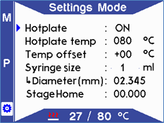
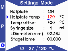
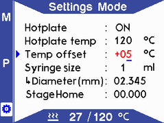
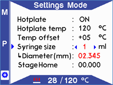
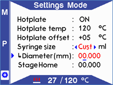
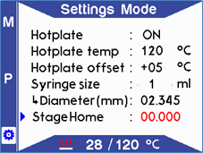
The Settings Mode allows the user to input parameters related to the hotplate operation, syringe properties and stage homing. Edit mode can be entered by pressing “OK” on the required line. Entering edit mode on any parameter will turn the text of the parameter red.
|
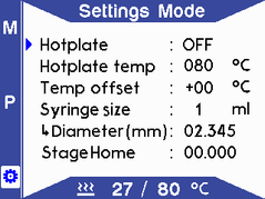 |
 Note: The Hotplate icon on the screen will blink RED while the hotplate is switched ON. |
 |
|
 |
Note: An external temperature sensor is required to measure the surface temperature (not supplied). The displayed temperature has the offset applied and therefore will appear higher than the set point temperature when a positive offset is applied. |
 |
Note: The selected syringe size is displayed in the upper right corner within Program Mode. |
 |
Note: If the diameter value is not set, a warning will appear on the screen to notify the user. |
 |
Note: To change the stage position manually, go to Manual Mode. |
 |
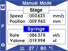
9.2.3 Manual Mode
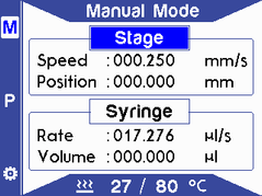
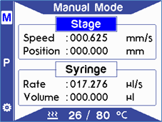
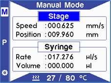
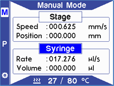
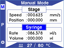
Manual Mode allows direct control over the syringe pump and stage positions. Entering edit mode on any parameter will turn the text of the parameter red.

WARNING: Pinch points and entanglement
The rotation of the lead screw/coupling and the movement of the plunger pusher present entanglement and pinch hazards. Care should be taken when the system is running.
|
 |
|
 |
|
 |
|
 |
|
 |
|
 |
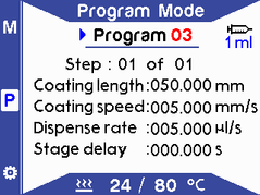
9.2.4 Program Mode
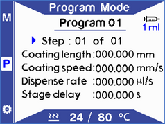
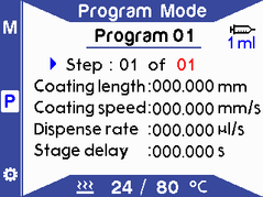
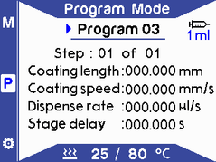
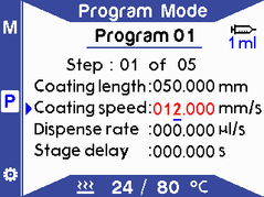
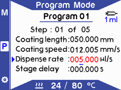
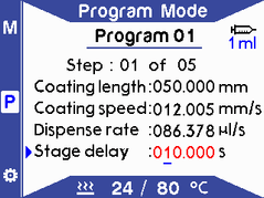
Program Mode allows the user to set up a coating process by defining several parameters. Press the button to enter Program Mode. Entering edit mode on any parameter will turn the text of the parameter red.
|
 |
|
 |
|
 |
|
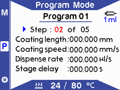 |
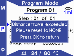
If the coating length is set above the maximum length allowed (100 mm), a warning will appear to notify the user. The system will automatically calculate the remaining allowed length and set it in the current step. |
 
|
|
 |
|
 |
|
 |
Note: The stage delay is used to delay the coating at the beginning of the step but allow the syringe to still dispense at the set rate. |
 |
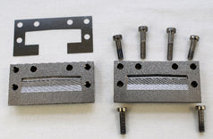
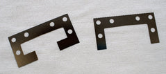
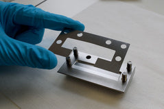
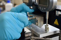
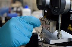
9.2.5 Assembly and Installation of the Slot Die Head
The slot die head can be assembled and installed while the unit is powered down.
|
 |
|
 |
|
 |
|
 
|
|
 |
|
 |
9.2.6 Levelling the Stage
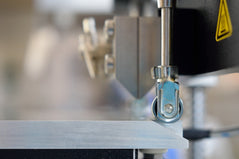
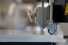
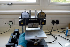
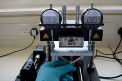
The digital height gauges used to level the stage have a resolution of 1 µm. It is not possible to level the stage to this accuracy. Recommended levelling parameters are given in the procedure below. If substrate heating is required, the hotplate temperature should be set, thehotplate turned on and the stage allowed to reach the set point temperature before levelling the stage.
|
 |
|
 |
|
 |
|
 |
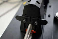
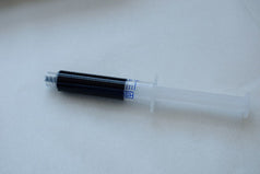
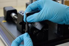
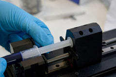
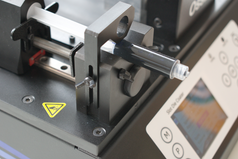
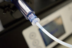
9.2.7 Installing the Syringe
|
 |
|
 |
|
 |
|
 |
|
 |
|
 |
|
 |
|
 |
9.2.8 Aligning the Slot Die Head to the Substrate
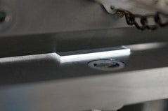
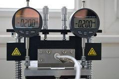
If substrate heating is required, the hotplate temperature should be set, the hotplate turned on and the stage allowed to reach the set point temperature before aligning the substrate (see Section 9.2.2:Settings Mode for hotplate operation instructions). There is a slight expansion of the stage when heated which may affect the alignment and the readings on the digital height gauges.

WARNING: Hot Surface
The hotplate is hot when heated and contact with skin can cause burns. Care should be taken when the system is running.
|
 |
|
 |
9.2.9 Forming a Meniscus
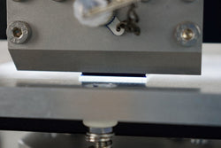
Before coating, a meniscus of solution should be formed across the width of the substrate by dispensing a small amount of solution in the Manual Mode. The slowest dispense rate should be used to avoid dispensing too much solution onto the substrate, which can cause defects. Solution should be pumped until a small amount comes out of the head and forms a meniscus on the substrate surface.Alternatively, a program step can be used to perform this automatically.
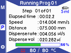
9.2.10 Running a Program

WARNING: Pinch points and entanglement
The rotation of the lead screw/coupling and the movement of the plunger pusher present entanglement and pinch hazards. Care should be taken when the system is running.
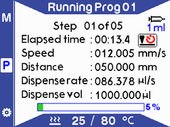 |
|
|
Note: If the stage delay is set in the program, the stage delay icon will appear blinking next to the elapsed time until delay time is up. If the coating speed has not been set for all off the program steps, a warning will appear to notify the user. Running will be aborted until the speed is set. |
|
|
 |
10. The Coating Process

WARNING: Volatile solvents
When using volatile solvents, place the slot die coater within a fume hood or controlled environment (e.g. a glove box).
To use the slot die coater, a general start-up procedure should be followed before coating should begin. There are several stages to this:
- Installing the slot die head (Section 9.2.5)
- Setting the hotplate temperature (Section 9.2.2)
- Levelling the stage (Section 9.2.6)
- Installing the syringe (Section 9.2.7)
- Aligning the slot die head with the substrate (Section 9.2.8)
- Forming a meniscus (Section 9.2.9)
- Setting the coating parameters & running the program (Section 9.2.10)
10.1 Gap Height
The gap between the slot die head and the substrate is important to coat a defect-free film. For an indepth explanation of this please refer to Ossila’s Slot Die Coating: Guide to Troubleshooting Defects.
To know the minimum gap height for coating a stable film you must first know what wet film thickness you are wanting to coat. If you are working from a dry film, you must begin by calculating the percentage volume of solids in solution. This can be done if the mass of the liquid, the mass of the solid, the density of the liquid, and the density of the solid are all known.

The needed wet film thickness (twet) can then be calculated from final desired dry film thickness (tdry):

As an initial number to work with, the viscous model approximation can be used. For this gap height (h) should be less than double the wet film thickness:

It should be noted that the gap height above is only true for solutions with capillary numbers greater than approximately 0.1 to 0.25. For low capillary number solutions, where the viscosity or the speed of the stage is low, the minimum gap height is controlled by the equation below, where 𝐶𝑎 is the capillary number. This means higher gap heights can be used for low viscosity solutions.

10.2 Worked Example
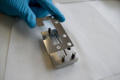
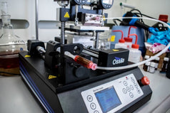
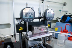
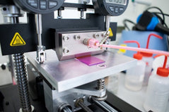
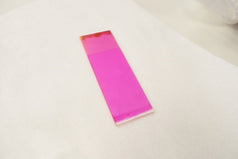
For this example, a fluorescent dye in 1,1,2,2-Tetrachloroethane (TCE) was used, at a concentration of 20 mg/mL.
|
 |
|
 |
|
 |
|
 |
|
 |
|
 |
11. Slot Die Coater Troubleshooting
Table 11.1. Troubleshooting guidelines for the Ossila Slot Die Coater
| Problem | Possible Cause | Action |
|---|---|---|
| No power/display | The power switch on the unit is in the OFF position | Check the connection and ensure the power is turned ON |
| The power supply may not be connected properly | Ensure the unit is firmly plugged in to the power supply and the plug is firmly connected to both the adapter and the working power socket | |
| The fuse on the rear panel has blown | Ensure the unit is unplugged. Check the fuse on the rear panel. If it has blown, replace with a suitably rated 5A slow blow fuse | |
| The power supply adapter has a fault | Contact Ossila for a replacement power supply adapter | |
| No obvious cause | If all the above causes have been considered, there may be a fault on the control board. Please contact Ossila for information | |
| Motor Stalled (Syringe Pump) | Syringe has hit first safety switch | There is not enough solution in the syringe and the moving part of the pump has hit the safety switch. Load more solution into the syringe so the plunger is further back and try again 
|
| Crash Warning | The secondary safety switch has accidentally been triggered | Switch the unit off and on again |
| The plunger pusher is triggering the secondary safety switch | Rotate the lead screw by hand to move the plunger pusher closer to the center of travel | |
| Internal fault in the secondary safety switch | If all the above has been considered there may be a fault with the secondary safety switch; contact Ossila for more information |
12. Related Products
Accessories
Compatible Substrates
Related Processing Equipment
Slot Die Coater


