Slot Die Coating: Theory, Design, and Applications

Slot die coating is an extremely versatile deposition technique in which a solution is delivered onto a substrate via a narrow slot positioned close to the surface.
A major advantage of the slot die coating method is the simple relationship between wet-film coating thickness, the flow rate of solution, and the speed of the coated substrate relative to the head. In addition, slot die coating is capable of achieving extremely uniform films across large areas. The Ossila Slot Die Coater, for example, can produce coatings with variations lower than 5% across many meters and a variation of < 50 μm variation over 100 mm (0.05%).
Slot die coating is one of many methods that can be used to deposit a thin liquid film onto the surface of a substrate. One of the main advantages of slot die coating over traditional techniques, like spin coating or dip coating, is that it can easily be integrated into scale-up processes including roll-to-roll coating and sheet-to-sheet deposition systems.
The technique itself offers high levels of coating uniformity, particularly when carried out inside a glove box, across the length/width of the coating surface and can deposit thin films with thicknesses ranging from a few nanometres to many microns. It can do this for a wide range of solution types and viscosities at rates ranging from a few centimetres per second to several meters per second.
Slot Die Coater

Introduction
In this guide, we introduce the concept behind slot die coating as a deposition technique and explain the theory that underpins the movement of solution within a slot die coater. This ultimately determines how the wet films are produced.
We also offer practical tips and outline the considerations that are needed to ensure high coating uniformity when working with slot die coating. This is followed by a discussion of some of the applications of this technique and what materials can be deposited via this method.
Finally, we discuss the idea behind the stable coating window that slot die coating operates within and relate this to observable defects that can occur within the film. By knowing how the processing window relates to coating parameters, it is possible to vary these to return to the stable processing region and remove defects from your coatings.
Overview of Slot Die Coating
Slot die coating is part of a family of techniques which are classed as pre-metered coating techniques. For pre-metered deposition, the final film thickness is dependent upon the rate at which solution passes through the system. This makes the theoretical determination of wet-film thickness very easy compared to other methods.
Due to the excellent processing window offered by slot die coating over other roll-to-roll compatible techniques, the method is of great interest for researchers who are transitioning from lab-scale fabrication of thin films to pilot-level production. Researchers in areas like polymer and perovskite photovoltaics, organic light-emitting diodes, quantum dots, and photonic structures (among many others) are now focusing on applying slot die coating as a deposition technique in their research in order to determine the feasibility of transferring their materials and device structures to a scale-up process.
Although slot die coating has many advantages, it is more complicated than other deposition techniques and the deposition quality can be highly sensitive to the processing parameters. There are, however, a number of design considerations that can help ensure high coating uniformity.
Slot Die Coater Quickstart Guide
Structure of a Slot Die Coater
The design and build of a slot die coater is based around providing a uniform delivery of solution to a given surface. This single simplified requirement can be difficult to manage when transitioning from uniformly coating small areas (of a few square millimetres) to coating larger areas (multiple square meters). To achieve this, the slot die coater is broken down into several specifically designed subsystems.
There are a total of four different subsystems:
- The metering system controls the flow rate of solution into a system
- The distribution system ensures the solution is spread evenly across the width of the coating
- The head-positioning system maintains the position of the head relative to the substrate
- The substrate movement system determines how the substrate is passed across the slot die head

The figure above shows a simplified roll-to-roll slot die system. A uniform flow of solution must be delivered from the metering system into the slot die head. This is important to provide a specified coating thickness, as well as a constantly uniform film across the length of coating.
Solution distribution is controlled by the slot die head. The dimensions of the internal cavity determine the distribution of solution across the width of coating. The size and dimensions of the slot die head opening are also important in creating a stable coating bead between the slot die head and substrate surface.
The slot die head is positioned above the moving substrate, and the height of the head relative to the substrate has a strong impact on the coating quality. Most systems are controlled either by micrometers or motorized stages; some advanced systems allow for the tilting of the head relative to the substrate so that a variable gap exists between the front and back of the head.
The final part of the system is how the substrate is moved relative to the head. In a roll-to-roll system, this is controlled by a roller which feeds the flexible sheet in at a given speed. In a sheet-to-sheet system, a linear stage can be used to move the substrate; this method is typically used for rigid substrates.
The way all these subsystems interact results in the formation of a stable coating, where the thickness of the deposited wet film is ultimately decided by:
- The speed at which the substrate passes the slot die head
- The rate at which the solution is dispensed from the slot die head
Solution Metering
Solution metering is required in slot die systems because the delivery of solution has a significant impact on the uniformity of the coating and the actual thickness of the film. The rate at which the solution is dispensed must be kept constant, as the rate at which the solution is dispensed from the metering system is directly proportional to the thickness of the deposited film. Any variation in flow rate then becomes a variation in the film thickness. High tolerances are therefore put onto the metering systems.
Another important aspect is how the solution is delivered by the metering system. Some methods of delivery provide solution in small discreet pulses rather than a constant rate and the frequency of these pulses can result in chatter defects appearing in the film.
In addition, the response of the delivery systems when used at varying pressures can have an impact on the rate at which solution is delivered. Pumps controlled by hydraulics or pneumatics can have problems with varying viscosity solutions as a result.
There are many ways to provide solution metering. The type of pump used is generally dependent upon several factors, including:
- Maximum volume of solution being coated
- Flow rates of solutions
- Accuracy of the flow rates
- Properties of the solution being pumped
- Cost constraints on the system
The types of pumps that are used for solution metering in slot die systems can generally be broken down into two types of displacement pumps:
- Peristaltic pumps, where the volume of a container of solution is reduced causing the solution to be displaced
- Rotary pumps, in which a rotating element transfers solution from one side of the pump housing to the other
The figure below shows simplified versions of a peristaltic pump (syringe pump) and rotary pump (rotary lobe pump), and how solution is displaced.

For small volume and low flow rates often seen in laboratory testing, simple peristaltic pumps (such as syringe pumps) are suitable. In these metering systems, a piston or plunger is used to displace the solution. The rate at which the solution enters the slot die system is dependent upon the rate at which the piston moves, and the diameter of the piston.
With a syringe pump, the displacement is controlled by electronic stepper motors which help keep the volume displaced independent of pressure - providing that the force required to displace the solution is less than the force that can be supplied by the motor. With these dispensing systems, the stepping rate becomes important in order to avoid the formation of defects due to the pulsed stepping of a motor.
For larger coating volumes and rates, these smaller systems are typically not well suited. Instead, rotary pumps connected to a large solution reservoir are used. In these systems, displacement is provided by a rotating element placed in a way that can restrict the flow of solution.
The volume pumped into a system is then directly related to:
- The speed at which the element rotates
- The volume of solution passed through in each rotation
In comparison to peristaltic pumps, the rotary pump method reduces the impact of pulses in the flow rate. However, as the displacement mechanism is in line with the solution protecting the mechanism against damage and also protecting the solution, contamination can become a problem.
Slot Die Head Designs
One of the most complex aspects of a slot die coating system is the design of the slot die head. The head controls the distribution of solution across the width of coating, the actual coating width of the film, and also helps determine the stability of the coating process.

The figure below shows the inside of a slot die head design. The head consists of several critical components - these include the inlet, manifold, land, slot, shim, and lip. Some heads can have multiple manifolds and lands (called pre-lands) to improve the distribution of the solution. However, increasing the size and number of these will also increase the dead volume within the system.

Inlet and Manifold
For the inlet, the position is typically in the middle of the system positioned near the top of the manifold. For slot die heads with a large width, multiple inlets can be used to reduce the size of the manifold needed, as well as the length of lands, pre-lands, and slots. Once the solution enters the system, it begins to fill the manifold.
There are multiple designs that can be used for this section of the slot die head, and it is this section which most strongly influences the distribution.

The figure above shows the most common designs for distribution manifolds and the different cross sections available. The simplest design is the T-shaped manifold, where the bottom and top edges of the manifold run parallel to the exit of the slot die. This creates a constant length (L1=L2) for the solution to travel to the exit slot and results in a drop in pressure away from the inlet.
This leads to lower solution flow rates closer to the ends of the manifold, uneven solution distribution over the width of the head, and different travel times for solutions.
To achieve equal flow rates across the width of the slot die head, the manifold can be shaped into a coat-hanger design. This is where the bottom edge of the manifold becomes closer to the exit of the slot die head (L1>L2 ) as the distance from the inlet increases. Although the flow rate of the solution becomes more uniform across the width when utilizing a coat-hanger design, the shape of the coat-hanger must be re-optimized for different flow rates and solution viscosities.
A modified form of coat-hanger design called a 'constant shear manifold' can be used, where the reduction in distance between the bottom edge of the manifold and the exit of the slot die is not linear. Instead, the initial reduction in distance is small, while closer to the outside edges of the slot die the distance reduces significantly (L1>L2>>L3).
This design allows for a constant flow rate across the width of the slot die head (independent of the solution viscosity and flow rates). The constant shear manifold, however, requires longer landing lengths than the other designs - and at the same time, the volume of the manifold is significantly larger. This increases both the size of the slot die head needed and the dead volume in the system, which leads to an increase in initial setup costs and operational costs over simpler designs.
Lands, Slots, and Shims
The pre-lands, lands, and slots within a die head are all regions where the flow of the solution is restricted via a narrow channel. The width of this channel and the length of the channel are crucial in controlling the drops in pressure within the slot die head, which helps control the stability of the wet film coating.
The flow of solution through these narrow channels is determined by the Pouiselle Flow equation (given by the equation below) where the drop in pressure within a slot die head (delp) is determined by the flow rate of the solution (V), the viscosity of the solution (mu), the channel length (L), and the channel width (b).
From this, it can be seen that the parameter with the largest amount of control over the pressure drop is the channel width. However, the cost of changing the length and width of channels is very high as would require the milling of a new head each time they are changed. It is possible to get around this by using shims of different thicknesses, which can expand the width of the channel.
By using shims of different sizes for different flow rates or solution viscosities, the pressure drop can be maintained at a fixed value.

In addition to controlling the pre-land, land, and slot thickness, shims can also be used to set the width of the coating. They can allow for the deposition of stripe patterns, and can be used as a meniscus guide to improve the definition of edges. By having the final slot thickness determined by the shim, it is possible to stop solution from flowing out of certain areas of a slot die head.
The figure below shows how a shim design can deposit 4 stripes of material onto a substrate using a single head. When depositing a stripe where the coating width is less than the width of the slot die coater head, the coating meniscus can spread out along the width due to capillary forces. This reduces the accuracy of the coating pattern, and can cause multiple stripes to bleed together.
To improve the edge quality, meniscus guides can be added. These guides are shims where a thin protrusion below the slot die head lip is used. The protrusions are placed where the stripe pattern is needed, and act to pin the meniscus to the shims rather than the lip. This stops the meniscus from spreading along the width of the head.

Lips
The final aspect of slot die head design is the lip. This is the area upstream and downstream of the exit slot of the head. In these regions, the meniscus is pinned to the slot die head, and the stability of these menisci can be strongly influenced by the design and positioning of these lips. The simplest change in the design of the lips is a change in the length of the lips, by increasing the length.
The figure below shows the three different geometries available for the lips. These are:
- The standard configurations where the gap heights of both the upstream or downstream lips are equal
- Underbite configuration, where the upstream lip gap is smaller than the downstream gap
- Overbite, where the upstream lip gap is greater than the downstream gap
The advantage of changing the configuration is that the stability of the upstream meniscus can be improved without changing the stability of the downstream meniscus.

Substrate Positioning
The positioning of the slot die head relative to the substrate is important in helping to stabilize the coating bead. In both sheet-to-sheet and roll-to-roll systems, the machining and tolerances of the carriage (or roller) that holds the substrate can have a great impact on the gap height. Either localized defects due to surface roughness, issues with the flatness of a bed, or the concentricity of the roller can cause changes to the gap height and coating bead stability over the length of the substrate.
The exact tolerances for the system will be dependent upon the solution you are coating and the processing parameters used.
When operating the system, the movement of the slot die head into position over the substrate can be controlled either manually or automatically. The advantage of automated control is that inline monitoring of the film quality can be used as feedback for the adjustment of the slot die head height.
In addition, automated movement enables rapid raising/lowering of the head for highly-defined leading and trailing edges in intermittent coating. Typically, the height of the gap is determined via the use of digital height gauges or micrometers. These are fixed to the head carriage, and measure the position relative to the top of the roller or carriage.
Slot Die Coater
Slot Die Theory
Knowledge of the underlying theory behind slot die coating is crucial in understanding how the operating parameters and slot die geometry interact to create a stable coating. High-quality coatings can be achieved only within a specific coating window, and moving outside of this stable coating window will result in the formation of defects - until eventually, the film will no longer coat.
By knowing the origin of defects within coated films, it is possible to know which processing parameters and slot die geometries need changing to return to the stable coating region. In this section, we will talk about:
- The theoretical basis behind the design of manifolds for improved distribution
- How the solution flows through restricted channels producing large pressure gradients
- How the shape and position of coating menisci are influenced
Solution Distribution
Distribution of solution through a slot die manifold is determined by several competing processes that drive the movement of fluid, and others that retard the movement of fluid.
These can be categorised as:
- The hydrodynamic pressure of the solution entering the manifold
- Gravitational forces helping to drive the solution down the slot die head
- Viscous losses
- Inertial acceleration of the fluid
The rate of flow of solution is determined by the pressure drop across a given section. Therefore, in order to understand the flow of solution across the manifold, the pressure drop across individual points needs to be calculated and the flow of solution determined. This can be done via computer simulation using finite elemental analysis, where the pressure drop is calculated at each individual element.
These pressure drops can be calculated using the equation below, where the pressure drop (dP) across a finite length of manifold (dx) is determined by four different terms:
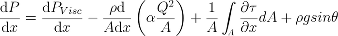
The first of these terms is the viscous losses in a fluid. These can occur due to molecule-molecule interactions inside the liquid itself, and are dependent upon the speed at which the solution is moving and the length over which the solution is being transported. This term dominates the pressure drop for high viscosities and very high flow rates.
The second term is the inertial acceleration of the fluid as it enters the section of manifold, the density (rho), the cross sectional area (A), and the velocity (d/dx) of the solution. The term in brackets is a correction factor that accounts for the direction of the solution flow with relation to the orientation of the cross section. This is important for sloped or curved manifolds, such as the coat-hanger or constant shear manifold.
The third term relates to shear forces at surfaces perpendicular to the flow of solution. This term is strongest for elements near the walls of the die-head. The stress tensor (tau) relates to the average velocity of the finite elements. Viscous losses occur when two adjacent regions have varying flow rates. Therefore, at cavity walls, the stress tensor is high due to the flow of particles being zero at this interface.
The final term of the equation is the pressure drop due to gravity. This term is only useful for cavities where the manifold is at an angle, such as coat-hanger and constant shear manifolds.
The figure below shows how finite element analysis across a coat-hanger manifold is used to break the system up into individual elements. Inside each element, the drop in pressure is calculated across the element.

Land and Slot Flow
Inside the lands and slots, the ratio of slot thickness to length is low enough that lubrication approximation can be used to predict the flow of solution.
This results in the flow being given by the Pouiselle equation (as seen below). At the boundary between the manifold and the slot, the pressure and flow rates must be continuous.
In reality, there can be a small loss of pressure during this transition between the manifold and the slot (due to changes in the flow direction), causing viscous losses and inertial forces. This can happen at abrupt interfaces that can cause vortices within the flow of the solution. These can be reduced by smoothing out the change in flow direction when transitioning from the manifold to the slot by using manifold cross sections (such as the teardrop-shaped design).
The change in pressure can be given by the pressure difference between the manifold and the slot die exit. Due to the conservation of mass, if the flow rate is fixed by a metering system, the flow rate through the slot must remain the same. Therefore, the pressure drop is regulated by the viscosity of the solution, the length of the land, and the thickness of the channel.
The channel length in a slot die coater is difficult to adjust, and requires the re-milling of an entirely new head to achieve. This makes using the slot length as a method of controlling the pressure drop between the manifold and the slot exit unrealistic, as the cost and time required to change this parameter is too high.
Alternatively, the viscosity of the solution can be modified, but this option is often not possible as many coating formulations require specific properties (such as material composition, carrier solvents, surface tensions, and even viscosities) to produce the optimal film properties.
The final method of controlling the pressure drop is to vary the channel thickness, as this term is cubic even small changes to this value will have a dramatic effect on the pressure difference.
In slot die coating systems, varying this channel thickness is the best way to achieve the desired flow of solution through the slot die head. This is done by using thin metallic shims that work to space the two heads a small distance apart. By using shims of different thicknesses, or stacking multiple shims of a given thickness, the spacing can be increased to the desired channel thickness.
Slot Die Substrate Lip Gap
In slot die coating, the head is placed close to the moving substrate so that once the solution exits the slot die head, it enters the gap between the head and the substrate. As the solution exits the slot die head, it enters one of two constrained channels in the upstream and downstream directions.
The flow of solution in these channels is given in part by the Pouiselle equation (as seen above), where the channel thickness is given by the gap height between the slot die lip and the substrate and the channel length is given by the length of the slot die lips.
Due to the presence of a moving surface relative to the slot die head, the flow of solution is not just determined by the Pouiselle equation. Due to boundary conditions for fluids in contact with a solid surface the flow rate of the solution must be zero relative to the solid surface at the interface.
As the slot die head is effectively stationary and the substrate moves at a set speed, this results in a varying flow rate between the bottom of the channel and the top. The flow rate varies linearly up the profile of the flow channel, this type of flow is known as Couette flow and can be determined by the Navier-Stokes equation.
Due to the Couette flow, the overall profile of solution flow between the upstream and downstream lips will vary as it will be a summation of the flow due to the pressure gradient (Pouiselle flow) and the shear force (Couette flow).
The figure below shows the superposition of the two flows for the upstream and downstream lips. It is the balance between these two flow dynamics that ultimately determine the positions of the upstream and downstream menisci, and the coating quality in slot die coating.

Upstream and Downstream Menisci
The two menisci that form within the upstream and downstream lip channels are responsible for the quality of the coating of the wet film in slot die coating. Both menisci should be pinned within the channel between the lip and the substrate.
If the menisci drift either towards the slot die exit or swell outside of the channel, defects in the coating will occur (see troubleshooting). When the menisci are pinned within the channel, the coating is said to be within a stable coating window.
The position of the menisci are ultimately determined by the balance between the pressure gradient and the flow of solution given by the Pouiselle equation and also the Couette flow from the shear force.
The figure below shows how the processing parameters of a slot die coating system can alter the position of the upstream and downstream menisci relative to each other, and how a stable coating window can be achieved for a wide range of processing parameters.
The gap-to-thickness ratio of the system is a parameter that relates the flow rate of solution, the speed at which the underlying substrate moves, and the lip-to-substrate height. The flow rate of solution and the gap height vary the pressure difference given by the Pouiselle equation. At the same time, the substrate speed will vary the shear forces and increase the Couette flow.
Increasing the gap-to-thickness ratio can be done via the following methods:
- Raising the height of the slot die lip relative to the stage, resulting in a drop in the flow rate due to the pressure gradient
- Reducing the flow rate of solution, also resulting in a drop in flow rate from the slot -die exit to the edges of the lip due to a drop in pressure gradient
- Increasing the speed of the substrate, increasing the shear forces acting on the solution
By increasing the gap-to-thickness ratio, the upstream meniscus is pulled back towards the slot die exit as the Couette flow dominates the position of the upstream dynamic contact point.

In the figure above, it can be seen that a pressure difference exists between the upstream and downstream lips. Under standard conditions, this value will be zero as the variations in atmospheric pressures over such small distances are insignificant. However, in high-end slot die coating systems, a vacuum chamber can be incorporated at the upstream lip - resulting in a lower pressure at the upstream lip compared to the downstream lip.
This causes an increase in the pressure difference in the Pouiselle equation for the upstream lip in comparison to the downstream lip. This results in more material flowing upstream in comparison to downstream. This allows for faster substrate speeds for a fixed flow rate and gap height while staying within the stable coating window.
It can be seen that the stability of coating is a simple balance between the flow rate from the slot die exit and the shear force due to the substrate moving. Both the upstream and downstream lips must form stable menisci in order for the coatings to be defect free. Outside of the stable coating window, there are many defects that can be formed (see troubleshooting).
Slot Die Coating Applications
The deposition of thin films with high uniformity is of great significance for a variety of different technologies. Slot die coating, with its ability to coat across a wide range of viscosities and at high web speeds, means that the technique can be used for advanced thin film manufacturing and also for low-cost, high-volume products. A wide variety of products use slot die coating as a thin film deposition method, including:
- Battery Technologies - Deposition of the electrolyte slurry in battery technology is being increasingly done via slot die coating. The extremely high viscosities of these solutions make other techniques unsuitable for coating on large scales.
- Optical Coating - Thin film coatings are seeing regular use in construction for the application of reflective and anti-reflective coatings on windows.
- Carbon Fibre - Nanocomposite materials containing carbon fibre can be coated using slot die coaters, these lightweight, mechanically robust materials are seeing use in aerospace and auto-mobiles.
- Anti-Static Coatings - Thin conductive films of PEDOT:PSS can be coated onto a wide variety of surfaces. These conductive films allow the dissipation of accumulated charges on the surface of an object.
- Thin Film Electronics - Thin film solution-processed semiconducting materials can be deposited by slot die coating. These semiconducting layers can be used to fabricate light-emitting diodes, photovoltaic cells, and even transistors.
- Conductive Films - Slurries of metallic nanoparticles (such as 2D nanowires & even carbon nanotubes) can be coated onto a surface to produce a conductive film to start the fabrication of thin film devices.
Troubleshooting
Although slot die coating has many advantages, there are several technical challenges that make it more difficult than standard coating techniques (such as spin coating).
This is due to the need to balance pressures at varying interfaces so that a stable meniscus can be formed during the coating process. Defect-free coating can only be achieved by coating within a stable window, and the variation of one of many parameters can cause the process to exit this stable coating region.
Obtaining defect-free coatings requires an understanding of the various different defects that can appear during the coating process. By knowing and being able to readily identify the defect, it is possible to pinpoint the origin of these defects.
The most important things to observe when troubleshooting defects are:
- Where the defects occur
- Frequency of the defects
- Defect size and shape
- When in the coating process they occur
Once these have been noted, it is possible to identify which type of defect has occurred. By changing the processing parameters, checking the equipment, and modifying the solution properties, these defects can be overcome - and users can begin to coat defect-free films using their slot die coating systems.
The following section gives an understanding of the most commonly-found defects, and provides a broad overview of their characteristics, origins, and methods that can be used to eliminate their presence.
Stable Coating Window
Slot die coating relies upon the formation of two stable menisci that can be seen upstream and downstream of the slot die exit. The position and angle of the meniscus are important for obtaining defect-free coating. The figure below shows the position of the upstream and downstream menisci during coating of a defect-free film.
The upstream and downstream meniscus becomes pinned at the ends of the lips, and these are then classed as static contact points on the slot die head. The upstream meniscus also has a second contact point with the substrate. This contact point is free to move, and is called the dynamic contact point. The shearing of the liquid due to the moving substrate causes a force directed downstream, which moves the dynamic contact point downstream towards the slot die exit. While downstream, the shear force causes a thinning of the liquid film. The second contact point for the downstream meniscus is assumed to be an infinite distance away, and is only a consideration during the start and end of coating.
The shape of the menisci and the position of the contact points are determined by two factors:
- The interaction between the shear force
- The pressure drop of a liquid flowing through a thin channel
The equations and parameters that determine the magnitude of these competing forces were discussed earlier in this guide. The stable coating window is a region where the sets of parameters used for coating, lead to the formation of upstream and downstream menisci (similar to the ideal ones shown above). Just outside of this window, specific defects are formed related to the shape of the meniscus. Going even further away from the coating window will lead to complete failure of the coating bead. The figure below shows the stable coating window for a slot die coating system.
The upstream pressure is the difference in pressure at the upstream meniscus in comparison to the downstream meniscus. In a standard slot die coater, this value will be zero - as at the boundary between the atmosphere and the fluid, the pressure must be equal. Therefore, both menisci have a pressure equal to atmosphere. However, with the addition of a vacuum box at the upstream lip, a pressure difference can be present between the upstream and downstream meniscus. The gap-to-thickness ratio is the ratio of the height the downstream lip is above the substrate, and the thickness of the wet film. This value is a maximum of two when no vacuum is present on the upstream lip - meaning that the thinnest the film can be is half the gap height.
Below the Coating Window - When the process drops below the stable processing window, the upstream meniscus begins to move towards the slot die exit. This starts with a gradual movement of the dynamic contact point and eventually leads to the static upstream contact point moving down the lip. When an air gap becomes present underneath the slot die exit, the presence of bubbles can occur through air entrapment. When the static contact point recedes to the slot die exit ribbing can occur as the downstream flow becomes disturbed by the formation of vortices.
Above the Coating Window - When the coating process goes above the stable coating window, in the presence of a vacuum box, the upstream static contact point begins to go past the confined channel of the lip. This results in a swelling of the meniscus and a formation of swelling defects (where excess material becomes present on the upstream lip) - causing severe variations in the thickness of the coated film and a poorly defined coating width.
To the Right of the Coating Window - When the coating process goes to the right of the window, the wet-film thickness is significantly lower than the gap height. Due to the high shear forces relative to the pressure of flow downstream of the slot die head, the wet film becomes significantly thinner than gap height. The meniscus begins to recede towards the slot die exit, and the formation of bubbles occurs as air begins to become entrapped within the film, further reducing the wet-film thickness (relative to the gap height) results in the static upstream contact point receding. This leads to the coating bead becoming destabilized locally - thus the film no longer coats, resulting in the formation of ribbing defects.
It can be seen that the formation of two stable menisci (situated within the lips of the slot die coater) results in stable coating of films. When there is an imbalance between the shear forces induced by the moving substrate and the pressure drop of a solution flowing through the constricted channel, these menisci change.
Slot Die Coater
Slot Die Defects
Slot die coating is a complex process, and obtaining a stable coating of a film requires a deep understanding of the physics behind the deposition techniques. There are two types of defects that can occur:
- Defects due to instabilities in the coating bead meniscus where the coating process exits the stable coating window. Altering of coating parameters will result in the return to the stable coating region.
- Or what could be classed as external factors either relating to the delivery of fluid, movement of the substrate, or the viscoelastic properties of the solution. These defects often require alterations to the coating system or fluid in order to overcome these issues.
The following section looks at the two categories of defects and shows commonly-occurring problems, the characteristic features of these defects, where they arise from, and the methods that can be used to remove these defects.
Chatter
Chatter is a defect which is present across the whole width of coating. This defect appears either at the same point in the coating, or at regular intervals. The characteristics of chatter are:
- A line where the thickness varies in comparison to the rest of the coating.
- A line where defects become more prominent in comparison to the rest of the coating.
- A defect occurring at evenly spaced intervals or frequencies.

The origin of this defect is due to either:
- The fluid delivery system having variations in pressure or flow rates
- The substrate roller/linear stage having pulsed movements or a defect on the roller
- Variations in the pressure within an upstream vacuum box
Fluid Delivery Systems - If chatter defects are due to the fluid delivery system, the reason is typically due to the pulsed flow of solutions. Displacement pumps rely upon the movement of discrete volumes of solution. This leads to a chatter defect frequency dependent upon the rate at which these discreet units are displaced.
For rotary pumps, this is a function of the RPM of the system. Conversely for other displacement pumps based on linear motors (like syringe pumps), this is dependent upon the stepping rate of the motor. This can be mitigated by switching to delivering the discrete volumes of solution at faster rates, either by higher RPM or higher rate of micro-stepping.
Pulse-dampening elements can also be added to the solution feed to smooth out the output of displacement pumps. Metallic piping can be replaced with plastic piping, which undergoes expansion and relaxation during the feeding of new liquids - effectively smoothing out the pulses.
Substrate Stage - Stage chatter defects depend on the type of system being used. In a roll-to-roll process where a roller is used, the shape of the roller or the motor driving the roller could be the origin of the defect. By checking the distance between defects to the circumference of a roller, it is possible to determine if the origin of the defect is due to the roller.
For linear stages (typically used in sheet-to-sheet deposition), the chatter could be dependent upon a defect in the stage surface or an issue in the stepping rate of the motor. If the defect appears in the exact same position of the substrate, the issue will likely be due to a localized defect on the stage surface. For defects occurring at regular intervals across the length, the chatter will likely be due to the motor.
Vacuum Boxes - In some systems, a vacuum box is incorporated into the upstream lip of the slot die head to overcome the minimum thickness limitations. Changes in the background pressure of the vacuum box will cause variations in the stability and positioning of the coating bead. Changes in the background pressure can be due to issues such as:
- Chamber leaks
- Problems with the vacuum pump being used
It can be difficult to relate the frequency of the defects in the coating to variations in vacuum pressure, as these may not always be regularly spaced if it is due to leaking.
Ribbing
Ribbing is similar to chatter. However, the defects appear along the length of the coating in regular intervals across the width of the coating. The characteristics of ribbing are:
- Lines along the length of coating, where the thickness of the film reduces in comparison to the rest of the film
- Typically consists of multiple lines across the entire width of coating
- Some ribbing may occur as single-line defects. The origin of these ribs are different compared to multiple ribs

Ribbing occurs when the upstream meniscus recedes towards the slot die exit. This can be due to either:
- High shear forces, due to fast substrate speeds moving the dynamic contact point downstream
- Low pressure at the slot die exit, due to low viscosities or large shim thickness
- Reduced upstream pressure due to a wide gap between the substrate and slot die head
- Localized defect on the head or slot die feed forming vortices within the flow
Shear Force vs Flow Pressure - The position of the meniscus is ultimately due to a balance between the shear forces at the substrate liquid interface and the pressure associated with flow through narrow channels. By balancing these two, the meniscus can be stabilized. The coating bead can be returned to the stable coating window by either reducing the shear force, or increasing the flow pressure. This can be done by:
- Reducing the speed of the substrate to reduce the shear force.
- Increasing the flow rate of solution to increase the flow pressure.
- Reducing the distance between the upstream lip and the substrate to increase the flow pressure.
If it is not possible to change the above parameters, other methods can be used to reduce the presence of ribbing. These methods are:
- Reducing the shim thickness to increase pressure at the exit of the slot.
- Increasing the viscosity of the solution to increase flow pressure.
- Adding a vacuum box to increase the upstream pressure gradient.
As these methods require a shut down of the coating process, they should be considered as the last options for removing ribbing defects.
Localized Defects - Sometimes the presence of ribs are due to localized defects on the slot die head - these can either be on the lip, or within the feed slot - and can result in the formation of localized vortices which will cause a localized drop in the flow rate. These defects can either be due to damage of the slot die head from mishandling, aggregation of material in the slot die feed, or poor design of the slot die head. Damage to the slot die head can be repaired by polishing the surface to remove scratches. To reduce aggregation, the system will need to be cleaned and the solution reformulated.
Neck-In
Neck-in defects occur across the length of coating, at the very edges. The characteristics of neck-in defects are:
- A gradual decrease in the coating width of the film across the length of travel of a substrate
- A thickening of the edges of the film, with the thickness increase at the edge becoming more predominant as the width of the coating decreases

The origin of the neck-in defect is due to:
- A transition from constrained flow of solution between the lips and substrate towards a plug flow results in a change in the flow dynamics
- Mismatch between the flow rate and the substrate speed causes acceleration of the fluid and shear forces
- Shear forces result in the contraction of the coating bead towards the centre leading to higher flow rates at the edges
Changes in Flow Dynamics - The change from the constrained-channel Pouiselle flow towards a plug flow occurs as the gap height between the lip and the substrate increases. This occurs when the solution can no longer form a meniscus with the slot die lip (when slot coating transitions to curtain coating). The greater the gap, the higher the degree of neck-in that occurs - therefore lowering the gap height can reduce the appearance of neck-in defects.
Solution Acceleration - Differences between the solution flow rate and the speed of the coated substrate can cause the solution to accelerate along the travel direction of the substrate. This results in the formation of shear forces that cause the edge of the curtain or slot bead to recede towards the centre of the coating resulting in neck-in. Lowering the speed of the coating web can reduce the appearance of neck-in if this is the cause, in addition a smaller shim thickness will increase the speed of solution exiting the gap allowing better velocity matching between the substrate and solution.
Solution Contraction - This can be affected by the properties of the solution. For example, solutions that have high viscosities and high surface tensions typically have a higher degree of neck-in occuring. These solution types have strong interactions between the solvent molecules. For solutions with high surface tensions, the addition of surfactants can help reduce these interactions.
Edge Defects
Edge defects can occur on all edges of a coating. However, when under constant operation in a roll-to-roll system, the front and back edges of the coating are not seen as an issue. The characteristics of edge defects are:
- Variations in the thickness at the edges of the coated films, typically appearing as a thickening of the edge areas
- Variations in the position of the coating edges. For leading and trailing edges, these are typically curved rather than straight; for side edges, these can go in and out along the length of the coating

The origin of edge defects is due to either:
- Transitioning between the coating being on or off is the main cause for edge defects in the leading and trailing edges
- Surface tension and viscoelastic properties of the solution can cause the movement of the wet film during the deposition and drying stages
- Differences within the surface energy of various regions on the substrate can alter how the solution wets to the surface
Trailing and Leading-Edge Transition - The main reason for trailing and leading-edge defects is the rate at which the coating bead can be stabilized and destabilized. By changing the processing steps to purposefully destabilize the bead at the end, this edge can be well defined. This can be done by stopping the flow of solution to the head - or even retracting solution from the bead by drawing solution back. The speed of the substrate can also be increased to rapidly shear the coating bead. For more advanced systems, the slot die head can be retracted from the surface to rapidly increase the distance between the slot die and the substrate. Combining all these methods can result in a very well-defined coating edge - especially when working on intermittent coatings.
Solution Properties - At lower viscosities, the surface tension of the solution dominates this edge thickening. By reducing the surface tension and improving the wetting of the solution onto the substrate, the edge thickening can be kept within the region of a few millimetres. For high-viscosity solutions, the surface tension's contribution to edge defects is minimal, and varying the surface tension of the solution is not likely to improve edge quality. For viscoelastic materials where compression and expansion of the solution occurs, swelling at the ends of the slot die exit can happen as the pressure drops. This can result in variations in the coating width and thicknesses.
Unfortunately, elimination of all edge defects is extremely difficult and requires complex engineering. Some examples of methods are: the use of air jets to remove the bead, doctor blades to shear the thick areas, or introducing solvent at the edge of the slot die exit to dilute the solution at the edge of the bead. Generally, an acceptable size for a coating edge defect is around a few millimetres, and many substrates take account of this by having sacrificial coating areas which can be removed.
Surface Treatment - The wet film can be pinned to specific locations to improve the definition of coating edges. This can be done by treating the surface of the substrate in specific locations where the film needs to be wet. One method is to use UV ozone treatment to reduce the surface energy of the substrate in a specific location. This will result in preferential wetting in the treated areas leading to well defined coating locations.
Generally, edge defects are only a major problem when dealing with large-scale production. In small-scale prototyping, the use of sacrificial areas (to allow for the presence of edge defects) is commonly used. However, in roll-to-roll or sheet-to-sheet processes (where throughput is high), thicker areas will have slower drying times, which could result in contamination of the equipment if these areas are still wet. In roll-to-roll systems, thicker areas can result in the web not being able to be wound properly - and when using contact printing methods further down the production line, the centre of the coating area may not contact as well as the outer edges.
Streaks
Streaks are a common feature in wet-film coating technique, and can arise from a wide variety of sources. The characteristics of streak defects are:
- Individual line defects that originate from a point and continue upstream - appearing similar to a comet. A build-up of material appears on the downstream face of the defect, while upstream a line of reduced thickness appears
- An elongated line with reduced thickness that extends along the length of the coating

The origin of streak defects are either:
- Substrate defects such as dust or dirt particles that obstruct the flow of solution forming streak defects originating where the dirt particle is present.
- Obstructions in the slot die head or at the lip can result in extended lines of reduced thickness, or even uncoated areas. These obstructions are either aggregates within the slot die feed, or dust particles big enough to become trapped between the lip and the substrate.
- Damage to the slot die head can result in the formation of permanent streak defects within the film, due to destabilization of the coating bead at that particular location.
Substrate Defects - The presence of dust and dirt on the surface of substrates is an inevitable problem when it comes to wet film-coating techniques. Thorough cleaning of the substrates will remove the presence of dirt and dust. However, dust particles within the air will re-contaminate the substrate over time. The chance of this happening can be reduced by working within a clean room environment, where the presence of dust particles is minimized. Inline processes often integrate high-pressure air jets or rubber wipers just before the substrate reaches the slot die coater, to blow or push away dust particles from the surface.
Obstructions - In areas where large dust particles are present and the gap between the slot die lip and the substrate is roughly the same size of these particles, obstruction of the upstream or downstream lip can occur. This results in a destabilization of the coating bead and the formation of a streak. The steps listed above to reduce and remove these dust particles from the substrate can be used however these are never 100% successful. Other methods (such as a rapidly oscillating slot die head) can be used to dislodge these trapped particles.
The other source of obstructions that form streak defects are those within the feed slot of the slot die coater - where the channel width is low. Here, any possible aggregates that form within the solution can become trapped and disrupt the flow of solution downstream. If aggregates become a significant problem with the solutions that you are working with, you may need to reformulate the ink to decrease the presence of aggregates. The simplest ways to reduce the chance of these obstructions is to increase flow rate through the head (to reduce dwell time), or increase the slot die channel width. More advanced methods can involve the addition of a heating element to the slot die head, or an internal wiper that can be quickly passed across the whole width of the feed channel to sweep away trapped aggregates.
One final source of obstruction is the presence of entrained air within the solution before it reaches the slot die head. This entrained air results in the formation of bubbles that can get trapped in both the feed slot, and between the lip and substrate. To help prevent this, the solution should be thoroughly filtered and degassed before it enters the system. In addition, connectors and adapters that are used to transport the solution should be checked for any potential leaks.
Slot Die Head Damage - Although the slot die heads are made from strong materials (such as stainless steel), damage to the head can occur in critical regions (such as the slot die lip). Slot die heads should be handled and stored with care to reduce the chance of any damage occurring - especially to the lip and feed channel. If any damage does occur, small scratches can be removed through the use of a low-grit lapping film. For large dents in the head, milling of the area can be done to smooth out the damaged region - or a complete replacement of the head may be needed.
Bubbles
Bubbles can appear in the film at any point in the coating. The characteristics of bubble defects are:
- A film defect that is round or elliptical in shape. This size of these defects can vary.
- The thickness of the film where the bubble defect appears will be significantly thinner, or may not contain any material.
- Position of defects along the width of the coating is randomized.

The origin of bubbles are either:
- Air entrainment in the original solution fed into the pumping system.
- Entrapment of air occurring from leaks within the fluid delivery system.
- Entrapment of air from destabilization of the upstream or downstream meniscus.
Air Entrainment - Air entrainment is the trapping of air in the solution before it enters the solution-metering system. This can occur for several reasons during the solution preparation, such as loading of the solution into the pumping reservoir, or through incorrect setup and purging of the lines with solution. The presence of bubbles is often exaggerated for high-viscosity solutions, as they have a longer lifetime. In addition, low surface tensions can result in the formation of more bubbles - especially if surfactants are used to produce these low surface tensions.
The solutions can be degassed before being put into the fluid delivery system. If there are problems with bubble defects, additional care should be taken when loading the solution into the fluid pump reservoir. The solution-metering system should be kept at a lower height than the slot die assembly, and bends in piping should be avoided in order to reduce trapping of air bubbles when initially flushing the lines.
Leaks in the Lines - When leaks within the line can occur, they can introduce bubbles into the solution before it enters the slot die head. These leaks are most likely to occur where connectors and adapters are used. Check that all of these are airtight - the use of PTFE tape (for sealing of threads) can help maintain a tight seal.
Meniscus Entrapment - When the coating process exits the stable coating region, the position of the meniscus will move inwards for both the upstream and downstream menisci. As the position of these menisci is fairly dynamic, the menisci can (within a localized region) oscillate between being stable and unstable. This can result in the trapping of air within the wet film, resulting in the formation of a bubble defect. By moving the coating process deeper into the stable coating window, these randomized fluctuations in the position of the menisci - and therefore the presence of the bubble defects - can be significantly reduced. Typically, to return the processing to the stable coating window, the gap height-to-thickness ratio should be reduced. This can be done by moving the slot die coating lip closer to the substrate, reducing the web speed, or increasing the flow rate of solution.
Leads and Tails
The process can also be complicated by the formation of leads and tails. A lead is an area at the beginning of the coating that has not reached a steady state. In this region, the coating is not at the correct thickness which limits the area suitable for testing devices. A tail occurs at the end of the coating and has similar issues. Careful priming of the slot die, along with the suitable coating conditions, can eliminate these problems.

Slot Die Coater
Closing Notes
Slot die coating is a powerful processing technique for depositing highly uniform films via a scalable deposition process. By tuning the geometric parameters of the slot die head, the solution properties, and the processing parameters, uniform thin films can be deposited over very large areas. Due to the process being a pre-metered deposition technique, the thickness of samples is determined simply by changing the flow rate of the solution or the speed of the web - whilst maintaining the process within a stable coating window.
However, understanding of the physics behind this stable coating window (and what parameters should be changed in order to return to this stable window) is a complex topic and care must be taken to avoid defects. In this guide, we have introduced you to the basics of how a slot die coater works, the processes required to design a slot die system, and the theory behind solution flow and the dynamics of the meniscus.
For help and support using the Ossila Slot Die Coater, please contact our customer care team, who will put you through to one of our technical experts.