Contact Resistance and Lead Resistance in Probe Stations
Minimizing electrical resistance is a key consideration when selecting components for use in a probe station. Lower resistance allows current to flow more easily through the probes to the measurement device, without affecting the measurement itself. There are multiple things that can contribute to resistance in measurement devices.
| Type of Resistance | What Is It? |
|---|---|
| Lead Resistance | The resistance of a wire, cable or lead connecting different components. |
| Contact Resistance | Resistance introduced by incomplete connection between the probe and measurement surface |
| Tip-To-Cable Resistance | Resistance between the tip of a probe and the wire connection point. |

Ossila's micromanipulator reports a path resistance of <0.3 Ω. This is the resistance between the end of the tungsten tip all the way to the measurement device. This value will vary depending on the quality of contact between probe and substrate, and type of cable used.
Contact Resistance
Contact resistance refers to the immediate resistance between the probe and the material you're measuring. Any contact resistance will impact current measurements, so can lead to measurement errors if not accounted for, especially when taking precise current measurement values.
The type of probe you pick will affect your contact resistance, but you need to balance this with other material properties. Beryllium-Copper Alloy tips are good for low-resistance measurements, but they are quite soft so can damage easily. Tungsten tips are stiffer and resistant to bending while still maintaining good electrical properties.
Your pad material will also affect your contact resistance. For example, gold is a popular choice for pad material and as a contact as it has low resistivity, therefore good contact resistance. However, this is quite a soft metal so can create some adhesion issues in higher force applications.
Aluminum pads are often used in wafer testing, where "scrubbing" of the probes against the wafer surface is needed to break through the oxide interface on the silicon wafer. This can create a build up of aluminum on your probe tip, affecting the contact resistance of future measurements.
Geometry of your probe and pad may also impact contact resistance, along with the surface roughness of your material or any oxide layers that might form. Contamination can also affect contact resistance. Initially, increased probe force reduces contact resistance but can ultimately ruin your measurement if you press too hard.
| Probe | Contact Resistance with Different Pad Type |
|---|---|
| Beryllium Copper | 100 µΩ gold, or 200 µΩ aluminum |
| Tungsten | 250 µΩ gold, or 250 µΩ aluminum |
Information taken from
Lead Resistance
Lead resistance is used to quantify the resistance of current flow through cables, wires and leads connecting components in a circuit. Lead resistance is dependent on the design, material and length of your lead.
An easy way to measure lead resistance is to short your wires through an ohmmeter and measure at the lowest resolution. Good quality leads will have a resistance of 0.2 Ω/m.
You can use co-axial cables to reduce lead resistance, but this is only suitable for AC measurements. Furthermore, you can reduce the thickness and length of your wire to reduce lead resistance, but this may impact the durability of your system.
Tip-to-Cable Resistance
In order to properly consider resistance in your probe station, you must also consider the resistance introduced at the connection between your probe and lead. Here, tip-to-cable resistance refers to the resistance from the probe tip through to the cable connection. This will account for any resistance through the arm of the micromanipulator and through the probe tip itself. This is sometimes referred to as the system resistance.
Two Wire vs. Four Wire Measurement
It's important to accurately assess the resistance introduced by any measurement equipment, especially for sensitive current or voltage measurements.
In a two-wire measurement, current is sourced and voltage is measured using the same pair of leads. While this method is simple and widely used, it includes the resistance of the test leads and contact points in the final reading. Four wire measurements are a better way to measure resistance through any component of your system. A four-wire measurement uses separate pairs of leads for sourcing current and sensing voltage. This configuration eliminates the effect of lead and contact resistance from the voltage measurement path.
Across device components or for specific devices, you can measure resistance using a probe station with micromanipulators connected to separate current source and voltage measurement channels of a source measure unit.
Micromanipulator

Further Reading
 Leakage Current: Definition, Examples and Leak Resistance
Leakage current refers to any unwanted current that flows outside of the desired circuit path, adding to the noise of a measurement. Leakage currents can arise from many things, such as:
Read more...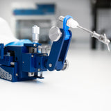 Connecting the Micromanipulator to the Source Measure Unit
This guide gives an overview of how to use the Ossila Micromanipulators with the Source Measure Unit, as well as some general tips and tricks for getting the most out of sensitive electrical probing measurements.
Read more...
References
- Contact resistance study of noble metals and alloy..., L. Chen (2007)
- Measurement and analysis of contact resistance in wafer..., D. S. Liu et al., Microelectronics Reliability (2007)
- Understanding Probe-Contact a-Spot Oxidation During Elevated-Temperature Wafer Test, Evaluation Engineering, Electronic Design (1999)
- Probe Contact Resistance: A Technical Bulletin for Probing..., Accuprobe