Four-Point Probe
Electrical Characterization, Lab Equipment,
Quick, Easy & Reliable Sheet Resistance Measurements
Precision system with interchangeable probes to adapt to your samples
Overview | Specifications | Features | Gallery | Software | In the Box | Related Products | Resources and Support
Accurately measure sheet resistance, resistivity, and conductivity of thin films in seconds using the Ossila Four Point Probe. With two probe types available, you can get the most out of your four point probe station:
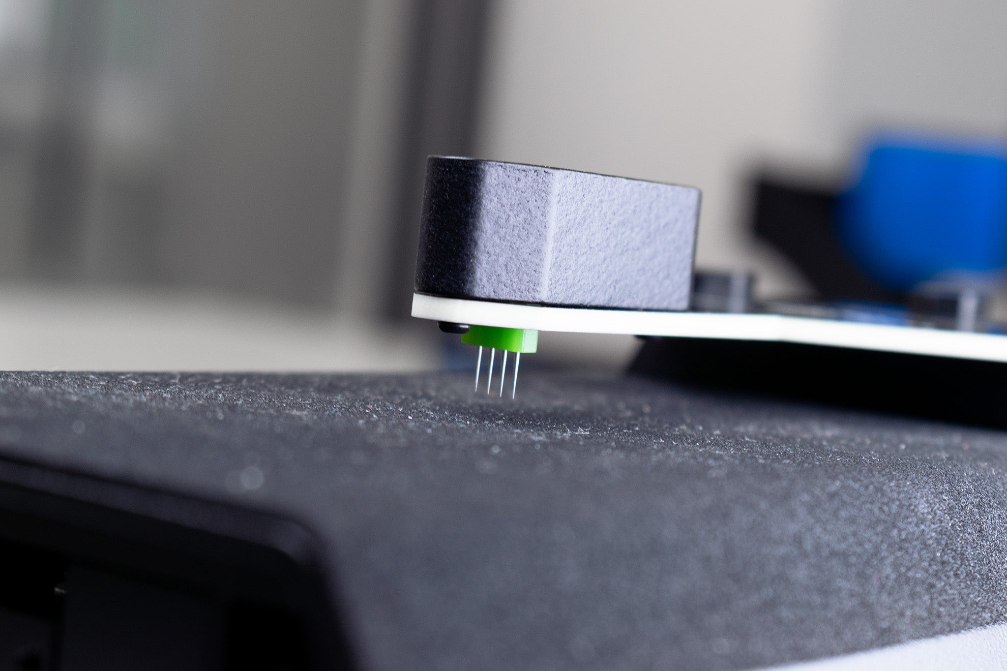
- Soft-tipped probes are suitable for delicate samples such as organic materials or very thin films. The spring-loaded, rounded contacts take high quality surface measurements without damaging your sample.
- Sharp-tipped probes are designed to pierce insulating oxide layers for reliable measurement of materials of hard materials like silicon.
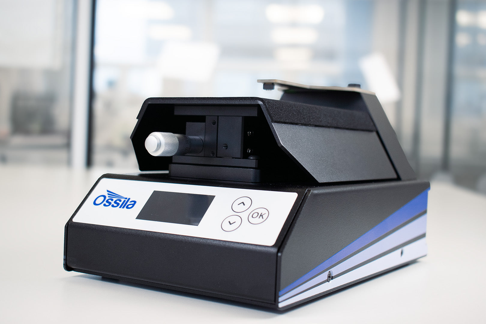
The Four Point Probe Plus comes with an integrated screen showing sheet resistance and conductivity at the touch of a button. This is ideal for use inside a glove box. Both models can also be PC controlled with free downloadable software. Choose the four-point probe for rapid and reliable material characterization.
Soft- or Sharp-Tipped Probes
Reliable measurements of many materials
Integrated Software
For easy sheet resistance measurements
Wide Current Range
For versatile sample measurements
Upgrade to Plus
In-built display for quick measurements
Towards more durable spacecraft: NASA used the Ossila Four-Point Probe to investigate the effects of space exposure on indium tin oxide coatings through sheet resistance measurements.
Key Specifications
| Voltage Range | ±100 μV – ±10 V |
|---|---|
| Current Ranges | ±20 μA – ±200 mA (5 ranges) |
| Sheet Resistance Range | 100 mΩ/sq – 10 MΩ/sq |
For more information on the current ranges, see our SMU specifications.
Probe Types
The soft-tipped probes reduce the potential of damaging delicate thin films with rounded tips and a larger surface area with a radius of 0.24 mm. The gold-plated probes are mounted on springs to allow them to retract into the probe head when making contact with the sample. This design spreads out the downward force and ensures that a uniform force of 60 grams is applied to the sample. The soft-tipped probes are not suitable for silicon or other materials which naturally form insulating oxide layers.
The sharped-tipped probes are designed for materials with naturally forming oxide layers, with a tip diameter of 0.08 mm. The sharp tipped probes are capable of piercing through oxide layers, directly contacting materials like silicon. The nickel-plated tungsten carbide probes can apply a maximum force of 197.43 gf to pierce the insulating layer for reliable sample measurements.


Please note: Your Ossila Four-Point Probe will require screen firmware version 1.1.0 or newer to use the sharp-tipped probe head. You can download the latest firmware from our website.
Sheet Resistance
| Sheet Resistance | SMU Accuracy* | Precision | Measured at Range |
|---|---|---|---|
| 100 mΩ/sq | ±8% | ±3% | 200 mA |
| 1 Ω/sq | ±2% | ±0.5% | 200 mA |
| 10 Ω/sq | ±1% | ±0.5% | 200 mA |
| 100 Ω/sq | ±1% | ±0.05% | 20 mA |
| 1 kΩ/sq | ±1% | ±0.03% | 20 mA |
| 10 kΩ/sq | ±1% | ±0.02% | 2000 µA |
| 100 kΩ/sq | ±2% | ±0.05% | 200 µA |
| 1 MΩ/sq | ±8% | ±0.5% | 20 µA |
| 10 MΩ/sq | ±30% | ±5% | 20 µA |
*The probe head can introduce up to 4% additional measurement error.
Four-Point Probe Features
Choose Probe Tips That Fit Your Sample
Soft- or sharp-tips are available to accurately measure sheet resistance, regardless of sample type. Soft-tipped probes spread the downward force, and are perfect for measuring delicate thin or organic samples. The sharp-tipped probes can apply a higher maximum force to pierce through insulating oxide layers. Easily interchange between these heads to fit the measurement technique to your sample.
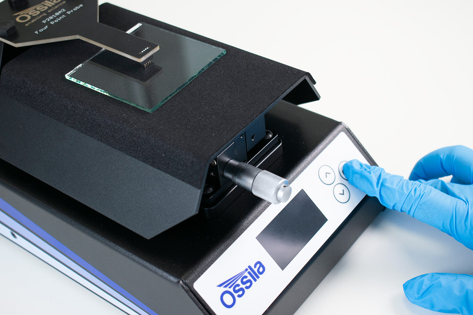
Quick Measurements Through Integrated Software (Plus model only)
To accurately measure sheet resistance, simply load your sample and press go. After inputting sample dimensions, you can also measure conductivity and resistivity without connecting to a PC. Get real-time data of the current and voltage between the outer pins and the voltage between the inner pins. Use either model with the PC software, which is always included for free.
High Accuracy
Positive and negative polarity measurements can be performed to calculate the average sheet resistance between positive and negative currents. This eliminates any voltage offsets that may have occurred, hence increasing the accuracy of your measurements.
Wide Current Range
Our four-point probe is capable of delivering currents between 1 μA and 200 mA, and can measure voltages from as low as 100 μV up to 10 V. The system can measure sheet resistances in the range of 100 mΩ/sq to 10 MΩ/sq, enabling the characterization of a wide range of materials.
Characterize Large Samples
The large stage area means you can characterize larger samples up to a 6 inch (152.4 mm) diameter. Larger samples are less reliant on correction factors and provide more accurate measurements when characterizing your materials.
Linear Translation Stage
With micrometer height control for simple and controlled soft sample contact. The manual knob makes it easy to achieve good electrical contact each time. Plus, the non-slip stage keeps your samples steady and ensures your delicate samples are not damaged by movement during characterization.
Four-Point Probe Gallery*


*Photos include both Original and Plus models
Software
Your four-point probe can be controlled using a PC, running our free, user-friendly Ossila Sheet Resistance Lite software. With the Plus model, you can also use the embedded software on the inbuilt data display. Both pieces of software can calculate appropriate geometrical correction factors for the sample geometry and the resistivity and conductivity of the sample to allow for extensive, accurate electrical characterization of materials (if you would like to record your data, you will need to use the Ossila Sheet Resistance Lite software).

The Sheet Resistance Lite software is supplied on the included USB memory stick along with a copy of the user manual and QC data. In addition, the latest version is always available to download for free from our website.
The Sheet Resistance Lite software saves data to comma-separated value (.csv) files, facilitating importing the data into your preferred analysis software. Advanced settings give you greater control over the measurment, allowing you to set voltage and current limits, perform negative polarity measurements, or use probes with different spacings.
Sheet Resistance Lite Software Requirements
| Operating System | Windows 10 or 11 (64-bit) |
|---|---|
| CPU | Dual Core 2 GHz |
| RAM | 2 GB |
| Available Hard Drive Space | 270 MB |
| Monitor Resolution | 1440 x 900 |
| Connectivity | USB 2.0, or Ethernet (requires DHCP) |
Additional Specifications

Physical Specifications
| Four-Point Probe Dimensions (W x H x D) | 145 mm x 150 mm x 240 mm (5.71" x 5.91" x 9.45") | |
|---|---|---|
| Soft-tipped probes | Sharp-tipped probes | |
|---|---|---|
| Probe Spacing | 1.27 mm (0.05") | 1.6 mm (0.063") |
| Rectangular Sample Size Range |
Long edge minimum: 5 mm (0.20") Short edge maximum: 152.4 mm (6") |
Long edge minimum: 6 mm (0.24") Short edge maximum: 152.4 mm (6") |
| Circular Sample Size Range (Diameter) | 5 mm – 152.4 mm (0.20" – 6.00") |
6 mm – 152.4 mm (0.24" – 6.00") |
| Maximum Sample Thickness | 8 mm (0.31") | 5 mm (0.2") |
Resistivity and Conductivity Range
As the system measures the sheet resistance of a sample, a general range of measurable resistivities or conductivities cannot be given. This is because the measurable resistivity range depends on the thickness of the sample being tested. The resistivity of a sample can be calculated from its sheet resistance and thickness using the following equation:

The system is capable of measuring between 100 mΩ/sq and 10 MΩ/sq, so if we use these values in the formula above with a sample 50 nm thick, then the resistivity (conductivity) range that can be measured by the system will be 5 nΩ.m to 500 mΩ.m (2 S/m to 200 MS/m). If the sample is 400 µm thick, then the resistivity (conductivity) range of the system is 40 µΩ.m to 4 kΩ.m (250 µS/m to 25 kS/m). Below is a table of the resistivity and conductivity ranges of the system for samples with thicknesses of different orders of magnitude:
| Coating Thickness | Resistivity Range | Conductivity Range |
|---|---|---|
| 10 nm | 1 nΩ.m – 100 mΩ.m | 10 S/m – 1 GS/m |
| 100 nm | 10 nΩ.m – 1 Ω.m | 1 S/m – 100 MS/m |
| 1 µm | 100 nΩ.m – 10 Ω.m | 100 mS/m – 10 MS/m |
| 10 µm | 1 µΩ.m – 100 Ω.m | 10 mS/m – 1 MS/m |
| 100 µm | 10 µΩ.m – 1 kΩ.m | 1 mS/m – 100 kS/m |
| 1 mm | 100 µΩ.m – 10 kΩ.m | 100 µS/m – 10 kS/m |
In the Box
- Ossila Four-Point Probe with head(s) and stage
- Integrated source measure unit
- Inbuilt data display with sheet resistance measurement capability (T2001A5 only)
- 60 x 60 mm (2.36" x 2.36") glass substrate coated with 400 – 450 nm of FTO
- Power adapter (24 VDC)
- USB Driver with QC test report & QC test data
- USB-B cable
Accessories and Related Products


Resources and Support
 What Four Point Probe Features Do You Need?
Building on the reliable source measure unit, the Ossila Four Point Probe is an instrument that makes measuring sheet resistance as straightforward as possible for users. Without complex calibration or set up, you just put your thin film into the four point probe station and immediately get reliable sheet resistance, conductivity and resistivity values for your thin films.
Read more...