An Introduction to Quantum Efficiency

External Quantum Efficiency | Internal Quantum Efficiency | Quantum Efficiency Measurement | Reducing Quantum Efficiency

Quantum efficiency refers to the fraction of input energy that is converted into useful output energy:

Quantum efficiency is different for different devices but is typically dependent on the photon to electron ratio (or other physical entity involved in an interaction).
For light-emitting diodes (LEDs), the input energy is the number of electrons injected and the output energy is the number of photons emitted. For solar cells the input energy is the number of absorbed photons and the electrons generated as a result is the output energy.
| Application | LED | Solar Cell |
|---|---|---|
| Input Energy | Electrons | Photons |
| Output Energy | Photons | Electrons |

The quantum efficiency of solar cells may be given as a function of wavelength or energy. If all photons of a certain wavelength are absorbed, each one creates an electron-hole pair, and then the resulting charge carriers are collected at their corresponding electrodes, it’s quantum efficiency is 100%. This is impossible to achieve across all wavelengths. For example, the quantum efficiency of a solar cell below its band gap is zero as these photons do not possess enough energy to excite an electron into a higher energy state.
For LEDs, an exciton (bound electron-hole pair) must be formed through electron injection into the active layer. This exciton recombines radiatively emitting a photon. Again, 100% efficiency is impossible to achieve. Not all exciton recombination is radiative and any non-radiative recombination reduces LED quantum efficiency. Therefore in LEDs, quantum efficiency determines the amount of radiative recombination of excitons as a fraction of total exciton recombination.

External Quantum Efficiency
External quantum efficiency (EQE) measurements reflect the performance of the entire device, rather than just the optoelectronic (or “active”) material. EQE measures the input and output of a device, considering any losses due to either internal or external factors. This is often seen as the most practical quantum efficiency measurement, in terms of how a device will perform in situ.
Again, the exact definition and measurement of EQE is dependent on the device being measured. However, both LEDs and solar cells should aim to limit non-radiative recombination mechanisms or unwanted charge movement in order to increase their EQE.
Solar Cell EQE
The external quantum efficiency equation for solar cells is shown here, where the number of electrons that flow through the external circuit (the output) is divided by the number of incident photons:

| Jph | Short-circuit photocurrent density generated under monochromatic light illumination | λ | Wavelength of the monochromatic light |
| I | Intensity of the monochromatic light | e |
Elementary charge |
| h | Planck's Constant | c | Speed of light in vacuum |
| ν | Frequency of monochromatic light |
This equation is the opposite to the light-emitting diode EQE equation. The aim with increasing a solar cell’s EQE is to maximize both photon absorption and charge carrier extraction.
For solar cells, EQE measurements can be used to resolve and quantify the spectral mismatch of short-circuit current density, Jsc. The mismatch occurs as the spectral photon flux of a solar simulator is never exactly equal to that of the sun. JSC is related to the EQE of the cell and the AM 1.5 spectral photon flux. It can also be used to assess or confirm the accuracy of a solar cell measurement system.
An example EQE curve of a solar cell typically extends from 300 nm to 1200 nm. The space above the EQE curve (blue shaded area) represents the fraction of photons that do not lead to current generation. Photons may be lost via reflection which is represented on the graph. Additionally, excitons generated after photon absorption may recombine, rather than separating and reaching their respective electrodes. This also contributes to a reduction in its EQE.
EQE of LEDs
The total external quantum efficiency, ηex, of a light emitting diode is determined by the ratio of electrons inputted and the photons outputted. In other words, the number of outcoupled photons per injected charge. The difference here from internal quantum efficiency is that EQE measures the photons that actually leave the device, not just those generated.

ηex is calculated by multiplying the internal quantum efficiency (ηint) with the extraction efficiency (ηext). One subsequent EQE calculation can be presented as:

| Extraction Efficiency | ηext | The ratio of the photons emitted out of the LED, to total amount of photons generated in the emissive layer. |
Photon extraction efficiency is used interchangeably with outcoupling efficiency. Both refer to the fraction of internally generated photons that successfully escape from the device into the external environment.
As such, the equation to determine EQE is sometimes written as:

| Out-coupling Efficiency | ηOC | The fraction of light that "couples out" of the device. |
| Radiative Recombination Efficiency | ηrad | The fraction of charge carriers combining in the light-emissive region of the LED device to produce a photon (radiatively) to those that recombine non-radiatively. |
| Electron-hole balance | γ | The balance of electrons and holes in the active layer |
| Photoluminescence Quantum Yield | PLQY | The fraction the number of photons emitted to the number of photons that have been absorbed. |
Where ηOC is equivalent to ηext, ηr is the same as ηrad and γ multiplied by PLQY is equivalent to ηinj.
The reference to PLQY here highlights an important point about optoelectronic devices. High PLQY means lower amounts of non-radiative recombination, which means any recombination of excitons (electron-hole pairs) in an isolated active layer will most likely be radiative. For LEDs, this directly translates to efficient light emission.
Internal Quantum Efficiency
IQE measures the "internal" efficiency of quantum conversion processes happening within the active region only, not considering external factors. This is used to investigate material properties.
Solar Cell IQE
By examining the fraction of photons absorbed by the cell (compared to those reflected) and any subsequent recombination mechanisms, the internal quantum efficiency (IQE) can be determined. The IQE provides insight into which wavelengths of light are lost due to parasitic absorption or where charge-carrier collection is inefficient. This detailed analysis helps identify performance bottlenecks in the solar cell, such as inefficient charge separation or non-radiative recombination losses within the material.
IQE of LEDs
The internal quantum efficiency of LEDs is used to determine the number of photons generated inside the active layer per input of electrons. The total internal quantum efficiency of an LED is calculated by multiplying the current injection efficiency (ηinj) and the radiative recombination efficiency (ηrad):

| Current Injection Efficiency | ηinj | The fraction of the electrical current (charge carriers) that is injected into the active layer |
| Radiative Recombination Efficiency | ηrad | The fraction of charge carriers combining in the light-emissive region of the LED device that produce a photon radiatively. |
Current injection efficiency is highly dependent on the balanced injection of holes and electrons that can radiatively recombine. If the ratio of electrons and holes entering the active layer is unbalanced this can lead to non-radiative losses (such as Auger recombination), reducing efficiencies. Significant excess of a particular charge carrier can lead to leakage without contributing to recombination.
Quantum Efficiency Measurements
Measuring a Solar Cell's EQE
EQE measurements for solar cells requires a specific EQE set up. This can consist of:
- A broadband light source: Xenon, White light LED or Solar Simulator.
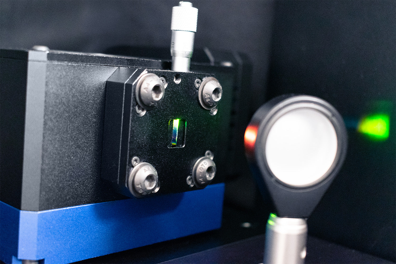
- Monochromator: To split light into component wavelengths before exposing to sample.
- Tunable light source: This combines the light source and monochromator in one instrument. However, the intensities from these sources might be a little low.
- A calibrated photodiode or photodetector: This acts as a reference device to measure the light intensity at each wavelength without any sample interaction.
- A beam splitter: To split the incoming light source if measuring the reference photodiode and solar cell device simultaneously.
- Test board: To hold under a small reverse bias and measure output current. Will require optimized placement to maximize absorption and minimize reflection. Additional optics and lenses can help with focussing the light source on the sample.
- A current measurement system: For the electrical measurements. A source measure unit with dual channels will allow you to measure the reference diode and solar cell simultaneously. Alternatively, you can just measure the reference photodiode, then measure the solar cell, manually comparing the data after.
- A chopper/lock-in set up: The irradiance at each wavelength reaching your sample could be quite small, so this set up may improve your signal-to-noise ratio.
- Integrating spheres: Can be used to minimize impacts of reflected or transmitted light.
EQE can be calculated from the ratio of the device current to the reference current, and normalised to the quantum efficiency of the reference photodiode at each wavelength.
Measuring LED EQE

When evaluating the number of photons produced per electron injected, we examine the photon flux and the injected current over a given period of time:

| Photon Flux | Φ | The number of emitted photons per unit volume per second. |
| Injected Current | I | The number of charge carriers (electrons and holes) injected per second |
Photon flux is the total optical power divided by photon energy. Therefore, at a given wavelength (λ), photon flux can be determined:

where h is Planck's constant and c is the speed of light.
There are several approaches to measuring the EQE of LEDs:
- Positioning a photodetector near the LED to measure emission. With this approach, it’s important to maximize light collection, so the photodetector must be positioned in the forward hemisphere, at the maximum collection angle, while reducing edge effects or unwanted reflections. This option may miss emission if the angle is wrong.
- Collect all photons emitted from the sample within an integrating sphere and channel into a spectrometer.
- Positioning a photodetector at a large distance from the device. This is helpful for applications where forward facing emission is important, such as display technology.
- You can also use a spectroradiometer instead of a photodetector, if you accurately measure device area.
When measuring EQE, using an aperture mask reduces effects of edge contributions or scattered light. It is often a good idea to investigate the angular distribution of emission to assess where best to place measurement equipment, especially if using new device architectures. However, this isn’t necessary if using an integrating sphere.
For LEDs, QE must be quoted with the carrier density its measured at, so EQE is often plotted as a function of current density or luminance. Plotting EQE as a function of luminance gives a good insight into how the efficiency of an LED varies with brightness. Prior to EQE measurements, an I-V-L characterization should be performed to determine the device's luminance as a function of current and establish appropriate operating conditions. An LED’s quantum efficiency should be measured over several magnitudes of luminance to more completely understand its emission characteristics (such as current leakage, peak EQE, droop, etc).
Reasons for Quantum Inefficiency
Reduced Quantum Efficiency in Solar Cells
Solar cells experience inefficiency factors similar to other organic electronic devices, such as LEDs, including:

- Non-radiative recombination mechanisms: loss of charge carrier species before they reach an electrode
- Auger recombination: energy of a photoexcited carrier (electron or hole) is transferred to another carrier rather than being utilized for current generation. This energy transfer typically results in the excitation of the second carrier, which then relaxes back to its ground state by emitting energy as heat, rather than generating an electrical current. Auger recombination becomes more significant at high carrier concentrations, such as under intense illumination or in highly doped regions of the solar cell.
- Shockley-Read-Hall (SRH) recombination: occurs when defect states within the bandgap act as recombination centers. These defect states can trap charge carriers, allowing them to recombine with carriers of the opposite type (electrons with holes). SRH recombination is particularly prevalent at material defects, impurities, or at interfaces between different layers, where trap-assisted surface recombination can occur. It is a significant source of inefficiency, especially in materials or devices with poor quality control or high defect densities.
- Charge carrier leakage: This occurs when electrons and holes are not confined within the active region of the solar cell, causing electrons to "leak" over the barrier and recombine with holes outside the active layer. This type of loss is often related to poor design of the solar cell's energy band structure or insufficient barrier heights at the interfaces, which fail to adequately confine charge carriers within the desired region.
- The energy barriers for electrons and holes are also considered to be important in determining the device quantum efficiency.
Other issues include:
- Photon reflection: occurs incoming photons are not absorbed by the solar cell but are instead reflected off its surface. This reflection is caused by differences in the refractive indices of the materials at the surface (e.g., the air and the solar cell). As a result, the reflected photons are lost and cannot contribute to the generation of charge carriers.
- Photon absorption efficiency: the band gap of the active materials dictates which photons can be absorbed.
- Device design: the thickness of the layers and their architecture can greatly influence EQE
In LEDs
Whilst there has been a huge amount of progress in increasing the external quantum efficiency of LEDs over the years, low QE still remains an issue. Here are some of the factors that reduce external quantum efficiency in LEDs:
- Non-radiative processes that negatively influence the radiative recombination efficiency
- Auger recombination: Energy is transferred to another carrier rather than being emitted as a photon inside the active layer.
- Shockley-Read-Hall (SRH) recombination: Happens through defect states within the bandgap (inside the active layer) and also occurs at the interfaces (trap-assisted) and is called surface recombination.
- Charge carrier leakage: electrons can fly over the active region to recombine with holes outside of the active layer
- Production of photons outside of the desired wavelength range.
- Low Photoluminescence Quantum Yield (PLQY).
- Dipole orientation: The horizontal orientation of the emissive transition dipole moment can improve the light out-coupling efficiency by up to 50% relative to a random orientation.
- The energy barriers for electrons and holes are also considered to be important in determining the device efficiency. A larger electron injection barrier / hole blocking barrier and a smaller hole injection barrier favor a high EQE.
Monochromator

Learn More
 An Introduction to Photoluminescence Quantum Yield
Photoluminescence quantum yield (PLQY) is a measure of the efficiency of photoluminescence in a system. It compares the number of photons emitted to the number of photons that have been absorbed.
Read more... What Features Do You Need In A Spectroscopy System?
Some factors that you should consider when choosing an optical spectrometer are the range of wavelengths you need to measure, the size and weight of the instrument, and its data collection capabilities.
Read more...
References
- Blue light emitting diode internal and injection efficiency, I. E. Titkov et al., AIP Advances (2012)
- Measuring the internal quantum efficiency of light-emitting diodes:..., J.-I. Shim and D.-S. Shin, Nanophotonics (2018)
Contributors
Written by
Application Scientist
Edited by
Application Scientist
Diagrams by
Graphic Designer