Potentiostat Circuit Diagram

Jump to: Signal generator | Feedback amplifier | Control amplifier | Current ranges | Current amplifier | Signal converter | Working electrode |
Reference electrode | Counter electrode
A potentiostat circuit diagram includes both the internal electrical components of the potentiostat, such as amplifiers, feedback loops, and voltage control circuitry, and the external components that make up the electrochemical measurement system (electrochemical cell and electrodes). This comprehensive representation is essential for understanding the interaction between the instrument and the electrochemical cell, as well as for analyzing how the applied potential and measured current are controlled and recorded during experiments.
A simplified potentiostat circuit diagram consists of several key sections, each of which is detailed below:


Signal Generator
The signal generator determines the applied voltage resolution of the potentiostat. It outputs variable DC (direct current) voltages via a digital-to-analog converter (DAC), which converts a computer-generated signal into a voltage. This allows the user to be able to accurately control the output voltage of the potentiostat via a computer.

Feedback Amplifier
The voltage feedback amplifier is perhaps the most important part of the potentiostat circuit. It measures the voltage between the working reference and the reference electrode, passing it to the signal converter to be sent to the computer. However, it also feeds this voltage to the negative terminal of the control amplifier. This enables the potentiostat, via the control amplifier, to keep the set voltage stable relative to the reference electrode.
It is important that the feedback amplifier does not overload the electrode voltage and disturb the electrochemical reaction, so a high input impedance with very low input current (pA) is used. The feedback amplifier also needs to be fast enough to allow the potentiostat to keep up with the rapid changes that can occur in electrochemical reactions and provide the feedback voltage to the output amplifier.

Control Amplifier
The control amplifier takes the voltage output of the signal generator and the feedback amplifier and outputs the voltage that will be passed between the working and counter electrodes. This is where the potentiostat accounts for any loss of voltage due to electrochemical reactions taking place in the cell. By using the output of the feedback amplifier as an input of the control amplifier, the signal is increased or decreased, allowing the device to keep the voltage between the working and reference electrodes stable.
The specifications of the control amplifier will determine the maximum voltage and current that the potentiostat system can output.

Current Ranges
This section of the circuit is for measuring the current passing through the working electrode and counter electrode. It consists of a single resistor or a set of resistors (the current ranges) and an amplifier. Each resistor corresponds to a different current range and can be toggled on or off to select the desired current range. Therefore, the number and resistances of these resistors will determine the currents that can be measured by a potentiostat.

Current Amplifier
When the current passes through a resistor it generates a voltage. The voltage is increased by the amplifier according to the selected current range and passed into the signal converter where it is converted to a current measurement.

Signal Converter
The signal converter uses an analog-to-digital converter (ADC) to convert the output of the voltage feedback amplifier and the current amplifier into a digital signal that can be interpreted by a computer connected to the potentiostat.


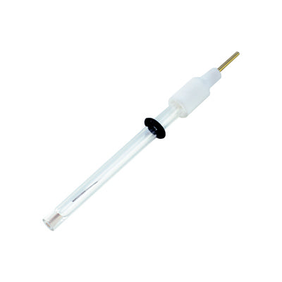
Working electrode
The working electrode is the primary electrode in an electrochemical system. It is where the applied voltage enters the system, and where most electrochemical reactions and electron transfer take place.
Measurements of potential and current in an electrochemical system involve the working electrode for both two and three-electrode systems. In two-electrode systems the potential and current are measured between the working and counter electrodes. In three-electrode systems, a potentiostat measures the potential between the working and reference electrodes whilst the current is measured between the working and counter electrodes.
Platinum is the most common material used for working electrodes due to its electrochemical stability and ease of fabrication. Other commonly used materials include gold, carbon, and mercury.
Reference electrode
By having a stable, known, and well-defined electrochemical potential, reference electrodes provide a constant for an electrochemical measurement.
They are used in a three-electrode system to maintain a stable potential against which the potentiostat measures and controls the working and counter electrodes. This is achieved using materials with well-defined electrochemical potentials, typically chemically separated from the reactions occurring during the measurement. When a voltammogram of such a system is plotted, the potential is that which is measured between the working and reference electrodes.
In an ideal electrochemical system, zero current will flow through the reference electrode, enabling accurate measurements and control of the potential at the working electrode. This is achieved by the reference electrode having a very low impedance, ideally zero.

Counter electrode
Counter electrodes, also known as auxiliary electrodes, complete the circuit of a two or three-electrode system. As with the working electrode, platinum is the most common material used for counter electrodes due to its electrochemical and mechanical stability, and high electrical conductivity.
In two-electrode systems, the counter electrode is also used as the reference electrode. This requires it to have a much greater surface area than the working electrode to ensure that reaction kinetics at the working electrode are not inhibited by those at the counter electrode.
In three-electrode systems, the current is measured between the working and counter electrodes. The potential is not measured here, but is adjusted by the potentiostat to balance the electrochemical reactions occurring. Instead, the potential is measured between the working and reference electrodes, ideally with zero current passed between the counter and reference electrodes.
Sometimes the counter electrode is separated from the working electrode in a similar manner to the reference electrode to reduce the influence of reactions taking place at the counter electrode on those at the working electrode.
Potentiostat

Learn More
 Cyclic Voltammetry: Theory and Setup
Cyclic voltammetry is an electrochemical technique for measuring the current response of a redox active solution to a linearly cycled potential sweep between two or more set values.
Read more... Troubleshooting Cyclic Voltammetry
With our modern potentiostat and software package, the method is straight-forward to perform. But if run into unexpected problems, this guide can help you to identify the source.
Read more...Contributing Authors
Written by
Software Engineer
R&D Engineer
Edited by
Application Scientist
Related Products
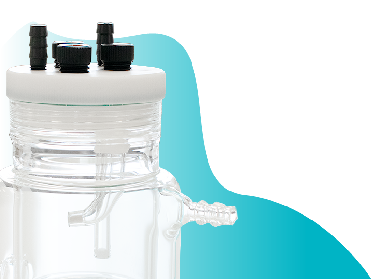
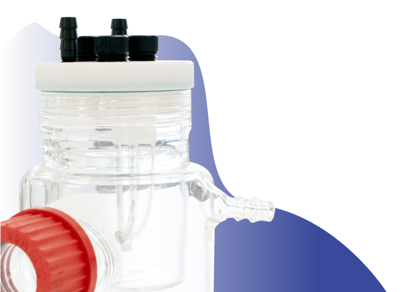
Photoelectrochemical Cells
Explore our range in photoelectrochemical cells.
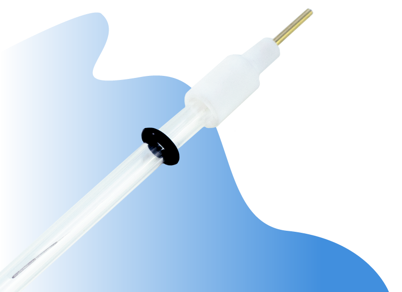
Electrodes
Explore our range of electrodes, including the glassy carbon working electrode.