Thin Film Deposition: Comparing Coating Methods

Thin films can be created through a range of coating methods including evaporation techniques and solution processing methods. Solution processing techniques uniformly coat a substrate with a solution, which then dries to make a thin film. Uniform and reliable thin film deposition is essential for the development and manufacture of solar cells and organic light emitting diodes, or other semiconductor devices.
The variety of thin film deposition methods available means some processes are better suited for certain applications. Solution processing methods in particular are attractive due to their potential for scalability.
From small-scale research to large-scale, commercial manufacturing, you must compare each thin film coating method considering both small- and large-scale applications. This allows you to make the right choice for your current needs, while understanding your options for scaling up in the future. Choosing the right coating method is essential to produce high quality thin film devices.
While a spin coater is suitable for small-scale lab research, successful thin films eventually require roll-to-roll (R2R) compatible methods. Slot die coating and spray coating serve as intermediate techniques, resembling R2R methods but adaptable to laboratory-scale operations.
It is also important to understand the drying process for your thin films. Several factors can be controlled to optimize the morphology of the final dry film.
Thin Film Deposition Methods
There are many different thin film deposition techniques used to produce high quality thin films. Each has its own advantages, drawbacks, and challenges, plus critical parameters to ensure a uniform coating, as well as ideal applications.
Understanding the difference between deposition techniques is essential to choosing the right coating method for your experimental needs. It is also important to consider the scalability of your selected technique and it's its compatibility with large scale manufacturing. Helpfully, most techniques are compatible with a wide variety of solutions, so there are several options to choose from.
Spin Coating
In spin coating, you deposit a solution onto a substrate, then rotate it at high speed. The centrifugal force from this constant acceleration, along with viscous drag and surface tension, causes the solution to spread evenly across the substrate. The thickness of the film is determined by the rate of rotation.
Spin coating reliably produces uniform films and works well with a wide range of solutions to produce many types of film, from polymer blends to small crystalline films. This makes it an extremely powerful and useful technique.
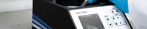
In thin film research, spin coating is the standard deposition technique. It is often used in processing photoresists on wafers and for thin film electronic devices (such as photovoltaics and light-emitting diodes). The Ossila Spin Coater is ideal for use in research and development laboratories which work on a wide range of thin film technologies.

Advantages
- Spin coating is a simple method that requires little training. It can create uniform films, ranging from nanometers to microns in thickness, across small, flat substrates.
- Drying times for this technique are often the fastest as drying is assisted by the air flow during rotation. Additionally, this means post-deposition heat treatment is not always necessary to complete drying.
- Overall, this is the most cost-effective for creating small batches or individual films.
Disadvantages
- Spin coating is limited to batch processing of small substrates, making it unsuitable for large-scale production. This limits its application in research and development.
- Additionally, the spinning process results in high levels of wastage because excess solution is cast off the substrate. This increases the cost as you scale up your thin film production.
- More complex thin films, including those with a curved or flexible substrate or gradient thickness, are very difficult to fabricate using spin coating.
Dip Coating
In dip coating, you immerse the substrate in the coating solution. As it is withdrawn, a liquid layer forms on the substrate. The solution will wet the film during immersion and dry upon removal through solvent evaporation. The final dry film thickness is dependent on withdrawal speed, air flow, viscosity, and evaporation rate.
Dip coating is often used in research on protein coatings, protective coatings, and tribological coatings. This technique has also seen some applications in the fabrication of organic photovoltaics. For example, it has previously been used to apply extremely thin and uniform self-assembled monolayers.

Advantages
- Dip coating is affordable, simple, and easily adapted to different needs. The Ossila Dip Coater is compact, making dip coating accessible in any lab space.
- Extensive training is not necessary, and specific film thicknesses can be obtained by controlling only a few parameters.
- Ideal for coating both sides of a substrate, dip coating is compatible with both flat or tubed substrates. Very uniform coatings can be achieved on a variety of substrates, with surface roughness of nanometers.
- Withdrawal speeds can be adapted to create gradient coatings or to optimize the process for low-concentration solutions.
Disadvantages
- To achieve a uniform coating, the volume of solution you use must be greater than the volume of the substrate. This can often lead to a high quantity of wastage from the solution reservoir.
- During the drying phase, the wet film is vulnerable to environmental factors. To control these factors, you should dry your films in a cleanroom or laminar flow hood.
- Depending on the solution, the film may need post-deposition heat treatment. This can increase the cost and reduce the scalability of dip coating. As the drying phase is separate, this can also result in material shrinkage which can lead to cracking in your films.
Slot Die Coating
In slot die coating, the solution is coated directly onto the substrate. The solution flows through a ‘head’ at a determined rate as the substrate moves relative to the head.
The wet film thickness is determined by the amount of solution placed onto the substrate. All other parameters, such as the solution flow rate, the coating width, speed, and viscosity, can be optimized to improve the uniformity and stability of the thin film deposition.
Slot die coating is ideal for both rigid and flexible substrates used for thin film electronics research, such as photovoltaics and LEDs.

Advantages
- You can produce uniform films with both high and low viscosity solutions, and you can achieve a range of film thicknesses. As you control the amount of solution deposited, there is little solution waste during slot die coating.
- Suitable for both rigid and flexible substrates, you can implement slot die coating in a variety of thin film applications. It is particularly useful for thin film technologies that require patterned coatings.
- Slot die coating is easily scalable and high coating speeds can be achieved. Additionally, it can be used in roll-to-roll processing. These factors make it an ideal choice for manufacturing applications.
Disadvantages
- Slot die coating is a complex process with multiple parameters that need to be optimized. To achieve defect-free coatings, you may need in-depth initial training unlike when working with other techniques.
- Most slot die coaters are often built for manufacturing. This means the initial cost is high, usually too high for thin film fabrication at the research and development stage. However, an affordable option is the Ossila Slot Die Coater, which is compact and low cost.
- The sources of defects are more difficult to diagnose due to the complexity of the technique. To achieve a uniform coating, first you must identify the stable coating window. This is the range of conditions that yield a uniform, defect-free coating. Typically, this requires multiple test runs and lots of operator experience.
- The solution lines require significant cleaning after every use.
- Overall, slot die coating can be slower, more expensive, and more difficult to optimize.
Doctor Blade Coating
Doctor blade coating (or blade coating) involves running a blade over the substrate to spread a solution evenly across its surface. There is a small gap between the blade and substrate which, along with the viscoelastic properties of the solution and the speed of coating, determines the thickness of the wet film.
Blade coating can be used across a wide range of research fields, including thin film electronics, battery technology, ceramics, and paints. It is well suited to applications that use high viscosity solutions and require thicker films. Blade coating is often used as a prototyping method for slot die coating, as it is less precise.

Advantages
- Blade coating is a simple technique which is inexpensive to set up while producing a high throughput. As you deposit solution in a semi-controlled manner, there is lower amounts of solution wastage.
- You can optimize a variety of factors (e.g. substrate speed or gap size) to produce films of different thicknesses or at different speeds. Blade coating is also suitable for solutions with a wide range of viscosities, and both rigid and flexible substrates.
- You can easily produce relatively uniform films. For example, automated blade coating systems such as the Ossila Doctor Blade Coater allows you to start making large area films quickly and easily.
- Blade coating is scalable and ideal for thin film fabrication on an industrial scale.
Disadvantages
- Blade coating is not as precise as methods such as spin coating. Typically, you will not be able to create films with thicknesses below 10s of microns.
- The wet layer film thickness has poor reproducibility. The films you produce by blade coating may not be as uniform as those produced through other methods. Volatile solutions can evaporate too quickly and result in uneven surfaces.
- Contamination or blade damage can form streaks in the wet film as the blade is dragged close to the substrate.
Bar Coating
Bar coating is very similar to blade coating; solution is spread across a substrate by a cylindrical bar with wire spiralling around it.
The gaps between the wire and the substrate control how much solution is allowed through. This determines the film thickness. The process can be optimized by altering the bar height and pressure, deposition speed, and the solution concentration and viscosity. This can be achieved using manual bar coating (dragging a bar across a substrate by hand) or using automatic bar coaters such as the Ossila Bar Coater.
While bar coating is suitable for thin film research applications, it is a rarely used technique. It is often used in the same fields as blade coating because of the similarities between the two methods.

Advantages
- Bar coating is inexpensive and simple-to-use.
- You can coat both rigid and flexible substrates, even over large areas so the process is easily scalable.
- If your films require a lengthy drying time, bar coating may be a good match. Drying time can be well controlled with this technique.
- The technique is easily adaptable, making it uncomplicated to optimize your thin films. Multiwire and special wire designs allow you to change the film properties without changing the chemistry of the solution or completely overhauling the system.
Disadvantages
- Similar to blade coating, film thickness is limited to the diameter of the wire. Typically, the minimum thickness you can achieve is ~10 microns.
- Patterning or gradients are also not possible. The surface and thickness of the coating is determined by the bar structure and solution properties.
- If the system is contaminated, streaks can form in the wet film as the bar is dragged close to the substrate.
- Blade coating is a slow process. The maximum speed is determined by the rate at which the gaps can be filled via the capillary force. This means it is not very time-efficient if you need to produce thin films at a large scale.
Spray Coating
Spray coating, also called spray deposition or spray forming, is an alternative deposition technique used in research and industry. Within a spray coater, the coating solution is broken up by a stream of pressurized gas, then dispensed in a continuous flow of fine droplets.
The final film thickness depends on the surface tension and viscosity of the solution, the properties of the gas flow and nozzle, the wetting of the solution, and the coating distance and speed.

Advantages
- Spray coating is a quick method for depositing thin films. It is easy to achieve multi-layer coating because each layer is made up of small, fast-drying droplets.
- Similar to other methods, you are in control of the volume of solution deposited. This results in minimal wastage.
- You can coat large areas of substrates and can coat substrates with uneven or curved surfaces.
Disadvantages
- One disadvantage of spray coating is the difficulty in patterning. Using a mask to create patterned films can waste large amounts of solution.
- This technique cannot achieve the same thin film uniformity as the other techniques. The process of film formation relies on the coalescence of individual droplets to form one continuous film.
- It is also harder to control thin film thickness using this technique.
- These systems can be expensive to install and require significant optimization time. The lines require significant cleaning after every use.
Thin Film Deposition Comparison
By understanding each technique’s advantages and disadvantages, scale, and challenges, you can choose the right technique for you. Below is a table to assist you in deciding what is the best thin film processing method for the current stage of your project.
| Spin Coating | Dip Coating |
Slot Die Coating |
Blade Coating | Bar Coating | Spray Coating | |
|---|---|---|---|---|---|---|
| Relative Cost |
Medium |
Low |
High |
Medium |
Medium |
High |
| Scalability | Not Possible | Limited | Scalable | Scalable | Limited | Scalable |
| Complexity of Process | Low | Low | High | Medium | Low | Medium |
| Uniformity of Films | High | High | High | Medium | Medium | Low |
| Thickness Achieved | Nanometers | Nanometers | Nanometers | 10s of microns | ~10 microns | Nanometers to microns |
| Patterning In-Situ | No | Gradient possible | Gradient and simple 2D patterns possible | Gradient possible | No | No |
| Coatable Surfaces |
Small, flat substrates only |
Complex, rigid shapes |
Flexible or rigid substrates |
Flexible or rigid substrates |
Flexible or rigid substrates |
Flexible or rigid substrates, curved or flat surfaces |
| Compatible with Roll-to-Roll Processing | No | Yes | Yes | Yes | Yes | Yes |
| Solution Wastage | High | High | Low | Moderate | Moderate | Moderate |
| Drying Times |
Fast |
Slow but increased with curing chamber |
Slow but increased with heating |
Slow but increased with heating |
Slow but increased with heating |
Fast |
| Coating Speeds | Very slow | Slow | Fast | Fast | Slow | Fast |
The selection of a thin film processing method is a crucial step which can have a considerable influence on the success of your project. The information available should help you select the most appropriate method for your project and prepare you for challenges that arise when scaling up your thin film production.
Spin Coating vs Slot Die Coating
Spin coating and slot die coating are both common and popular techniques. However, they both have different benefits and challenges.
Producing a Uniform Thin Film
It is easier to produce a uniform thin film using a spin coater. It is a very controlled deposition method and solution is distributed quickly and evenly with little training or user input.
There are a lot of factors to optimize when slot-die coating. This can often be a long process and will need to be optimized for each solution and substrate combination you are using.
Coating Area Size and Scalability
Spin coating is ideal for research and development applications to produce small, individual films.
However, slot die coating addresses many of the problems with spin coating.
- You can coat large areas
- Similar to continuous coating methods, not limited to batch processing.
- Slot Die coating is compatible with R2R techniques and large scale production.
Waste
In spin coating, roughly 10% of the solution is used to produce the film, the rest is discarded from the substrate.
The amount of solution lost during slot die coating is minimal in comparison to spin coating. In slot die coating, all of the solution is coated onto the substrate. Therefore, you can more easily estimate an accurate wet and dry coat thickness from simple calculations. As the coating thickness can greatly impact the devices performance, this is an advantage of slot die coating in device experiments.


Drying Thin Films
A vital aspect of the coating process is the drying stage. The way you dry your coating can significantly impact the coating's morphology and subsequent performance, especially within devices like OLEDs, perovskite solar cells or organic solar cells. Drying can also play a part in the final uniformity of your coating. Therefore, understanding what can affect this key step is essential to optimize experimental results.
Evaporation Theory
The thin film formation process is heavily influenced by evaporation. It can determine the coating uniformity, coating adhesion to the substrate, and the strength of the coating.
Evaporation occurs at a liquid-vapor boundary when the pressure of the vapor is below the pressure of the liquid. In case of wet film processing, it is the solvent that evaporates.
For this to occur, the solvent particles need to be close to the surface of the wet film and need to have a sufficient energetic driving force to leave the coating layer.
As solvent evaporates, the solid materials within the wet coating become more concentrated until the final dry film is formed. The evaporation process therefore determines how the solid materials come together to form the final dry film.
Key parts of evaporation theory are Fick’s diffusion laws and Boltzmann energy distributions. Ficks Diffusion Law states that the greater the difference in concentration of a species between two points (∇C), the greater the rate of diffusion. Applied to evaporation of thin films, the lower the concentration of solvent molecules in the gas phase, the faster the rate of evaporation.

Ji is the rate of diffusion, or material flux, of a species and has the unit of moles per area per second. D is the diffusivity of a species and has units of length per second. This is a measure of the speed at which a species will diffuse. Ci is the concentration of the species. For a one dimensional profile above a liquid-vapor interface, as in evaporation, this can be modified to:

Where k is now the diffusivity with the unit of seconds. The difference between the partial pressure, Pi, and vapor pressure, PVi, of a solvent at points x2 (for example, the surface of the evaporating fluid) and x1 (the bulk of the wet film) provides the driving force for the rate of evaporation. This means that the higher the vapor pressure, the higher the rate of evaporation. In addition, evaporation rate can also be increased by reducing the concentration of the species in the surrounding atmosphere.
In order for a solvent molecule to evaporate, it must break interactions between neighbouring solvent molecules or the dissolved solute molecules. Boltzmann energy distributions consider the proportion of solvent molecules with an energy above the value required to evaporate. There is an empirical rule that if you increase the temperature by 10 °C, the rate of evaporation doubles.

Nucleation Theory
Nucleation is relevant to thin film processing because many crystalline materials can be formed by spin coating, such as perovskites for solar cells. It is the mechanism by which a less stable, supersaturated solution begins to form solid solute crystals, eventually forming a more stable system.
In thin film processing, this occurs when a drying film has evaporated sufficiently to create supersaturated, unstable conditions. Nucleation can either happen homogeneously within the solution or heterogeneously on a nucleation site, such as an impurity or interface. Thermodynamics and kinetics both play an important role in nucleation.
Thermodynamically, nucleation will only be spontaneous if the Gibbs free energy change is negative. This has two main contributions:
- The surface energy cost of introducing a new solid-liquid phase boundary. This poses a barrier to nucleation that will scale with the surface area of the nuclei (i.e., will increase with r2).
- The energy profit or release as a result of the volume of the nuclei being in the solid phase, at a lower energy than the surrounding liquid. This scales with the volume of the nuclei (i.e., will decrease with r3).
These two phenomena are competing, as shown in the Gibbs Free Energy graph below. Here, the energetic barrier to nucleation can be seen and the point of spontaneous growth is marked as E.

Classical nucleation theory states that the rate of nucleation, R (number/vol time) can be determined by the product of two expressions describing both the thermodynamic and kinetic factors.

The kinetic contribution is expressed with Z and j. Where Z is the probability that a nucleus will form a new phase rather than dissolve, and j (number/vol time) is the rate at which molecules attach to the nucleus. The thermodynamic contribution is the number of nucleation sites Ns multiplied by the probability that these are of a critical size, expressed as a function of the free energy cost of nucleation, the Boltzmann constant, and the temperature.
One theory that can explain how thin films form from a solution is Lamer nucleation. In this, supersaturation is dependent on the concentration of a solute compared to the solubility limit of the solute in the particular solvent. Lamer nucleation involves three stages:
- The solution's concentration exceeds a critical level (Cmin) as solvent evaporates, leading to spontaneous nucleation.
- Nucleation sites grow as solvent continues to evaporate.
- Eventually, the solute concentration drops below Cmin, preventing further nucleation, and only growth occurs.
Nucleation is how the solution responds as it moves to a more stable state. Nucleation rate, location, and growth are important factors to consider that affect the morphology of both spin coated and slot die coated films. Factors to consider when you are trying to control thin film formation include solvent choice, which affects crystallization speed, and wettability on the substrate.
Evaporation During Spin Coating
In spin coating, the evaporation and drying is a vital part of the coating process. It is directly influenced by the solvent properties and spin speed, as shown in the figure below.

In general, the evaporation rate of a spin coated wet film is higher than a slot die coated wet film. This is due to the spinning motion that keeps the atmosphere less vapor saturated, maintaining a driving force for evaporation. Higher spin speeds will increase the rate of evaporation, as will increasing the vapor pressure of the solvent used. However, you should be careful when using spin speed to change the rate of evaporation as it also affects the final film thickness.
Spin coating models first started to include evaporation with Meyehofer’s model, which simply introduced an extra thinning term, e, to account for evaporation. Other theoretical models aim to describe more complex behaviors arising from evaporation rate. For example, if the evaporation rate is high enough, this can lead to the formation of a top layer of high concentration. This crust can subsequently prevent further evaporation and trap solvent in the film. This often leads to undesired defects or wrinkling in your final film.
You can change the spin coating environment itself to alter these effects. For example, spin coating in a solvent saturated atmosphere has been shown to reduce evaporation rates influencing the morphology of spin coated polymer films. This is a less practical way to control evaporation during the spin coating process as you will require specialist equipment. Nevertheless, it is an effective method that does not have a large influence on other factors.
Evaporation of Slot Die Coated Films
In the slot die coating process, the drying phase occurs separately from the coating phase. Evaporation begins once the wet film has been formed. This has both complications and advantages for influencing the dry coating obtained.
One complication is that the surface tension and viscoelastic properties of the coating solution can cause the wet coating to expand or recede before the coating is fully dry. This results in a different dry coating width, and thickness, than expected.
Due to an increased surface area at the edge, the edges of the coating dry more quickly than the center. With the increased rate of evaporation at the edge, capillary forces cause a flow of coating to move towards the edge of the film. This results in a higher concentration of solids at the edge and hence a thicker edge region. This effect is commonly known as the ‘coffee ring’ effect, based on the pattern formed when a drop of coffee is left to dry.

Due to the linear nature of slot die coating, there is a significant delay between the application of the first and last regions of the coating. As a result, the first region to be coated dries before the last region to be coated. The wet coating and dry coating are separated by a drying front, which can lead to issues if it is moving at a different speed to the solution deposition. The drying conditions can be modified to ensure a consistent movement of the drying front across the coating. In turn, this minimizes the formation of pinholes, cracks, and surface roughness.

The presence of a drying front allows each part of the process to be optimized individually. This makes troubleshooting more intuitive, as you can observe when defects occur and correctly attribute them to the coating or drying phase.
Solvent Choice, Solution Concentration, and Additives
Solvent choice has a significant impact on the drying phase of your thin films. The higher the boiling point of the solvent, the slower the rate of evaporation. However, you must take care to ensure compatibility between the solvent and solids in the coating. Alongside this, the solvent you choose can also have unexpected effects on the adhesion of the coating to the substrate, coating durability, and coating flexibility.
You can use a mixture of multiple solvents to tune the solution's boiling point and achieve an ideal evaporation rate. Typically, this is challenging as the obtained boiling point is not just a weighted average of the boiling points of the solvents used. Various other effects, such as changes in solution viscosity and surface tension, can make achieving a desired evaporation rate using solvent blending challenging.
Solution additives, such as drying accelerators and retarders, can increase the rate of evaporation. The mechanism by which these additives affect the rate of evaporation varies depending on the exact additive used. Normally, the solution viscosity and surface tension are modified, or the desired change can be achieved through a catalytic effect.
Before implementing changes of this nature to the coating solution, you should fully consider what you hope to achieve by changing the composition and the likely effect of any changes on your final film.
Drying Techniques
Various methods can be used to change the rate of drying and final film morphology, without changing the chemical composition of the coating.
A common drying technique involves drying the coated substrate on a hotplate, or inside a furnace or oven. The evaporation rate is increased when the temperature increases, reducing the drying time.
Additionally, if the hot plate temperature is above the glass transition temperature of the material in the coating, the coating can crystallize. This process is called thermal annealing. The resulting thin film morphology or crystal structure have a key influence on the device performance, particularly in the application of solar cells and batteries.
You can also implement this process under vacuum conditions, known as vacuum annealing. The presence of the vacuum prevents the sample from reacting with O2 in the air, which makes this process essential for air sensitive materials. Additionally, the vacuum pressure quickly and uniformly draws out solvent from the wet film. This is useful if you are drying large-area films.
Air blades, or air knives, are also often used to enhance the drying of large area films. The air blade blows air over the surface of the coating, removing solvent saturated air and providing a steeper concentration gradient for evaporation. You can even use an air blade with nitrogen, which is ideal for oxygen sensitive materials.

In addition to drying, you can use air blading to remove defects from the surface of the coating. The high pressure air can flatten local peaks and fill in local troughs, removing subtle coating imperfections.
The air blade can also lead to convective motions forming within the wet coating which alter the crystal structure obtained. Interestingly, the use of an air knife can favor the formation of crystals across the width of the coating, rather than vertical growth into the bulk coating. It is important that you have a steady stream of air because inconsistent flow can cause rippling effects in the dry film.
Large Scale Deposition
The scale of thin film production, or future scalability, is a crucial factor you need to consider when choosing a technique.
The majority of devices in development are small-scale devices which are fabricated using spin coating. In order for these thin films to be produced on a large scale, methods that are compatible with continuous processes must be used.
Scaling Up Different Techniques
Spin coating is good for small-scale procedures that require well-defined film thicknesses. However, it is difficult to apply spin coating large-scale manufacturing processes, and it wastes large amounts of material. The size of the substrate you can spin-coat has two main limits:
- The size or safe spinning speed of the spin coater.
- The increasing differences in forces at each point as radius increases, leading to non-uniform films.
While spin coating is a well-established method, the inefficiencies are highlighted with the increasing demand for high-volume production. From this demand, more scalable and efficient methods, such as slot die coating, are gaining attention.
Slot die coating has many advantages over spin coating which allow for greater flexibility in large scale applications. If a solution needs to be printed over a large area, slot die coating may be your best option. Unfortunately, these processes are fundamentally different, so knowledge of spin coating techniques cannot be transferred to the slot die coating process.
Alongside slot die coating, dip coating was developed for use in large-scale manufacturing, and can be used to evenly coat large area substrates. However, this requires a large reservoir of solutions which can become easily contaminated and result in large amounts of waste. While large area substrates can be easily coated using dip coating, it is a batch technique so is not compliable with continuous or roll-to-roll processing. These factors ultimately limit its scalability.
For continuous processes, blade coating is an option alongside slot die coating. Blade coating requires far less solution than spin coating does, making it significantly less wasteful. It is also very simple and easy to study in terms of kinetics and morphologies. The main disadvantage is its difficulty in generating patterned substrates (where only certain parts of the surface are coated).
When moving away from spin coating to a larger-scale technique, it is important to remember that the kinetics of film formation can fundamentally differ between different techniques. Depending on how quickly the thin film is deposited and how quickly the solvent evaporates, the layer will form in different lengths of time, and possibly with different morphology. As a result, the conditions that are optimal for spin coating are likely not optimal for a different deposition technique.
Roll-to-Roll Processes
Continuous processes with reduced waste are favorable for large-scale manufacturing of thin film devices. This is because they can be incorporated into a roll-to-roll (R2R) system.
R2R processing is a manufacturing technique where a flexible substrate is passed between large rollers and layers are coated in subsequent steps. R2R slot die coating unwinds a substrate from a first roll, applies coating with a slot die, dries it, and then rewinds the substrate onto a second roll.
Unlike small-scale slot die coaters that handle coatings a few centimeters in length, R2R slot die coating can cover areas that are kilometers in length. R2R processing is seen as the ideal method for large-scale processing as it can coat large areas very quickly and can combine several different printing or coating techniques.Arguably, the closest methods to R2R processing techniques are slot-die coating and spray coating.

Producing large amounts of uniform thin films is an advantage of R2R processing. This technique is ideal for commercial production or for projects that need many samples for testing. Additionally, the length of the coated area reduces the significance of leads and tails. Samples produced using this method show what can be achieved on a commercial scale.
Challenges of Scaling Up
R2R slot die coating has similar challenges to small-scale slot die coating, including finding the stable coating window. Alongside this, the increased operation time can result in changes to the solution during the process. Agglomeration or sedimentation of the solution can alter the dry thickness of the coating. In turn, this may impact the performance of the thin film device. Unwanted variation in the coating over time is known as 'drift', and it is hard to prevent or control. Innovative control techniques and feedback loops are only recently being implemented into R2R technology.
Due to the size of the equipment, cost also becomes an obstacle. R2R slot die coating has a high purchase cost and requires a large amount of coating solution and substrate. The high capital and operating costs make R2R slot die coating unsuitable for many laboratory scale experiments. Usually, access to R2R equipment can only be gained through central institutions or industrial partnerships.
Printing Thin Films
Beyond slot die coating, printing techniques are often the next step in scalable manufacturing. They are particularly useful when fabricating patterned thin films at a large scale. Printing techniques are compatible with R2R processes which makes them ideal for manufacturing large areas, while simplifying the complexity of patterning films.
Printing techniques include screen printing, flexographic printing, gravur printing, and inkjet printing.
Screen Printing
Screen printing uses a screen mesh pressed against the substrate to produce a pattern. This requires a high-viscosity, low-volatility solution, which can restrict the applications in OPVs. The deposition of electrodes (e.g. by using silver paste) through printing is particularly favorable to avoid high-temperature evaporation steps under vacuum.

Flexographic Printing
Less commonly, electrodes can also be printed using flexographic printing. This can also easily produce a patterned film by using a combination of engraved rollers. It is advantageous due to easier patterning and faster coating when compared to slot die coating. Flexographic printing can also use less viscous solutions than screen printing, which allows for more applications in the context of OPVs.

Gravure Printing
Gravure printing is a similar process that uses a combination of engraved rollers, which is able to produce very thin layers. Whilst gravure printing is advantageous due to speed and high resolution, the ability for complex patterning is limited.

Inkjet Printing
Inkjet printing, applied to OPV fabrication, has a high resolution, ease of patterning, fast printing, and minimal waste. However, there remains significant complexity related to nozzle clogging, solution additives, drying conditions, and circulation systems that restrict easy optimization.

Spin Coater
Learn More
 Spray Coater Equipment: Working Principles and Uses
A spray coater is a piece of equipment that facilitates the coating of a solution onto a surface using spray coating methods. Spray coating involves breaking up a coating solution into tiny droplets and directing this spray towards a coating surface using pressurized gas. As the droplets hit the surface, they coalesce to form a continuous film.
Read more... Spin Coater Advanced: Upgrades and Specifications
The Ossila Spin Coater Advanced offers more control than the classic spin coater in a wide range of areas including: enhanced user profile capacity, improved speed stability and range ,extended spin times, higher chemical and thermal resistance
Read more...Additional Reading
- M. A. Aegerter & M. Mennig. Sol-Gel Technologies for Glass Producers and Users.
- Rossander, L. H. et al. In-line, roll-to-roll morphology analysis of organic solar cell active layers. Energy Environ. Sci. 2411–2419 (2017)
- Evaporation rate in spin coating - Birnie, D. P., & Manley, M. (1997). Combined flow and evaporation of fluid on a spinning disk. Physics of Fluids, 9(4), 870–875. https://doi.org/10.1063/1.869519
- Mokarian-Tabari, P. (2010). Spin coating in a saturated solvent atmosphere. Controlling the morphology of spin coated polymer blend films. PhD thesis, University of Sheffield.
Contributing Authors
Written by
PhD Student Collaborator
PhD Student Collaborator
PhD Student Collaborator