It looks like you are using an unsupported browser. You can still place orders by emailing us on info@ossila.com, but you may experience issues browsing our website. Please consider upgrading to a modern browser for better security and an improved browsing experience.
Designing a Glove Box
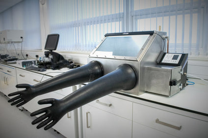
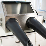
The Ossila Laboratory Glove Box
A glove box is a critical piece of equipment in many processing labs. There are several important components to consider when designing a glove box. Glove boxes need:
A sufficient maintenance system to keep inert gases low.
At least one clear panel to see the contents of the chamber
Gloves which allow you to manipulate things inside the chamber
A small, separate chamber (antechamber) allow you to bring items into and out of the glove box.
Glove boxes should be designed to reduce leakage as much as possible. Leakage can occur through:
Physical leaks in the system (holes, insufficient seals, etc)
Ingression of moisture and oxygen through glove box materials
An important part of designing a glove box is not just achieving inert conditions, but maintaining them. Glove boxes are designed in one of two ways to maintain low levels of moisture and oxygen over a long period of time.
Purge glove boxes - These regularly replace internal gas with fresh inert gas to remove contaminants.
Regeneration glove boxes - These systems clean internal gas with a filtration system and reintroduce it to the chamber. These glove boxes also flush the chamber with inert gas, but not as often as purge glove boxes will.
Both of these systems require constant internal monitoring of several environmental conditions (oxygen level, moisture level, internal overpressure, etc). Integrated purging software will use readings from these sensors to determine when to purge and for how long.
Whether a glove box uses a regeneration system or a purging system depends on many factors. Larger glove boxes tend to use regeneration systems to limit the amount of fresh inert gas needed to maintain them. However, these regeneration systems are complex, require regular maintenance and increase the cost of these glove boxes substantially.
The Ossila Glove Box uses a series of automated purging systems which flush the chambers with inert gases whenever oxygen, moisture, or pressure readings go beyond certain limits. There are also several purge features that can be triggered by the user to allow you to control the environment as much as possible.
Reducing Leak Points: Seals and Gaskets
Two hard surfaces with and without sealant materials.
Stationary and Permanent Seals
At the interface between two hard surfaces, there will always be a pathway for gas to pass through. On a microscopic level, the two surfaces have a high degree of roughness relative to the size of gas molecules. For this reason, a softer material is compressed between the two surfaces to fill these gaps and reduce leaks.
For stationary and permanent joins, silicone sealants can be used along with mechanical fixtures to ensure a tight fit. Alternatively, metals can be welded together to create a seamless join.
However, there are a several parts of a glove box that require non-permanent seals, such as doors for pass-throughs and feedthroughs for service lines such as power supply. For this, gaskets are extremely useful.
A gasket is a sealing component, often made of rubber or other flexible materials, used to create a tight and leak-proof connection between two or more surfaces, typically in mechanical or industrial applications. There is no permanent deformation of the materials, so these can be used to form a tight reusable seal.
Seal Type
Uses in Ossila Glove Box
Permenant
Walls of glove box welded together
Walls of antechamber welded together
Non-Permenant
O-rings around glove box
Gaskets around window plates
Types of Gasket for Non-Permanent Seals
A gasket is a piece of material that can be placed between two surfaces to form a seal. In the context of a glove box, their main purpose is to create an air-tight seal against gas/liquids entering and leaving the system. There are many types of gasket each suited for different situations. The seals used in glove boxes are O-rings, flat gaskets, and welded permanent seals.
Flat Gaskets
Flat gaskets are used to form a seal between two surfaces as shown in the figure above. Flat gaskets can be cut to a wide variety of shapes, and they can be made from many types of materials. They are most commonly made with rubber and expanded rubber foams. Flat gaskets are often used for washers to help make seals, or rectangular joins such as windows and doors. They are especially beneficially when low clamping forces are used.
O-Rings
O-rings are doughnut-shaped mechanical gaskets that sit within a groove that is milled into one of the surfaces. These are usually made out of harder elastomeric materials such as nitrile or Viton. Compression of an O-ring creates an air-tight seal that can withstand high pressures and temperatures. These are often used in regions where high-pressure differentials occur such as inlet piping, or for the doors of vacuum chambers integrated into a glove box system.
Reducing Ingression: Permeability and Barrier Materials
The physical properties of materials used to construct a glove box will have the biggest impact on the amount of oxygen and moisture permeation that will occur. As we must keep these levels as low as possible, the choice of material is extremely important for each aspect of a laboratory glove box.
All glove boxes are slightly permeable; moisture and oxygen can pass through the walls of the glove box and enter the atmosphere inside the chamber. Ingress, in the case of glove boxes, is the diffusion of unwanted oxygen and water into a sealed chamber. Some materials are more permeable than others. For example, stainless steel and glass have much lower ingress rates than plastic. How susceptible your glove box is to contamination from the ingress of moisture and oxygen depends on the design of the glove box.
How Does Ingress Through Barrier Materials Occur?
When discussing ingress, we need to examine the permeability each material4. This is a measure of the total transport of matter through a system.4 Or in this case, the O2 or moisture through the glove box walls.
The ingress process can be split into several different steps. The figure below shows the stages of a permeant travelling through a solid barrier. First (Step 1), the vapour molecules must reach the first barrier interface, B1. Then, the permeant is absorbed at B1 (Step 2), before diffusing through the solid barrier (Step 3). The permeant then undergoes desorption at the B2 (Step 4) and diffuses away from the barrier (Step 5).
The processes in Step 2/4 are mainly determined by solubility, S, while step 3, is determined by the Diffusion coefficient, D0.
The different stages that a permeant must go through to ingress through a barrier material.
Steps 2 and 4 can be described by the following adaptation of Henry’s Law:
Where the Solubility, S, is determined by the partial pressure (pPM) of the permeant and Ksol is Henry’s law constant4–6. This essentially describes how quickly a permeant can be adsorbed or desorbed by the solid barrier.
The permeants movement through the solid barrier is governed by diffusion (step 3). This is often the slowest process; therefore it acts as the rate limiting step for permeability. This diffusion process can be described by Fick’s laws. Fick’s first law denotes the relationship between concentration gradient and movement of permeants across a space dx is:
Where J is the flux of permeants moving through the barrier, D is the diffusion constant, and dC/dx is the concentration difference across the barrier (from x à x+dx).
However, as permeant diffuses through a material, the concentration of the permeant at both point X and point (X+dx) will change. It is therefore necessary to consider how this process changes with time. This leads to Fick’s second law of diffusion:
Where EA is the activation energy, T is temperature and R is the gas constant. This EA essentially represents the energy required for a permeant to squeeze through a solid.7 This also means ingress depends exponentially on temperature.
The permeability coefficient, P0, is a product of a systems S and D0 values. This is the property used to describe a barriers permeability to a specific permeant.
How to Measure the Permeability of Barrier Materials
Transmission rates of O2 and water vapor can be measured using a gas transmission cell.
For O2 transmission rates, a thin layer of barrier material is mounted in the centre of the transmission cell to divide the two chambers11. An oxygen sensor is placed in one chamber, and this chamber is then purged with nitrogen gas to remove all O2. Meanwhile, high oxygen levels are maintained with a constant N2/O2 supply. The increase in O2 levels detected by the sensor as oxygen diffuses through the semi-barrier can be used to determine oxygen permeation per unit time, or the oxygen (gas) transmission rate (OTR or O2GTR).
Different methods of measuring Moisture Vapour Transmission Rate. A gas transmission cell (left) can be use to measure extremely low MVTR (1. N2/O2 or N2/H2O flow; 2. N2 flow; 3. Vent to atmosphere; 4. N2 flow + H2O or O2 to Sensor). Simpler methods such as the Desiccant and Water methods (right) can be used where moisture ingress is significant.
You can also use this method to track moisture ingress. Instead of using high oxygen levels in the first chamber, use wet nitrogen. This maintains high moisture levels and you can then use an infrared sensor to detect the increase in humidity.
Another common method to measure moisture vapor transmission rates is by using the desiccant or water methods (ASTM E96). For these methods, fill a dish with either desiccant material or water and cover with a barrier film layer. Measure this dish before and after a significant period of time. In the desiccant method, you use mass gain to determine MVTR through the barrier material. In the water method, you use mass to calculate MVTR. The desiccant and water methods are much simpler to construct, but using a gas transmission cell will determine MVTR and OTR more accurately.
The units used for these measurements will vary depending on how they have been measured. Some metrics are outlined below:
Moisture vapour transmission rate, MVTR, (or water vapour transmission rate, WVTR) is a measure of the rate of water passing through a film or barrier (usually per day). This is measured in g/m2/day. One way to calculate this is to measure the uptake of water via the change in mass of the material.11 However, different methods can give different values for MVTR11, so to state the conditions measured in is very important. MVTR is generally described using this equation12:
Where P0 is the permeation constant for the barrier, p1-p2 is the partial pressure difference of water across the material, R is the ideal gas constant, EA is the activation energy and T is temperature.
Moisture vapour permeability is a measure of how much moisture will penetrate a barrier per given thickness. Therefore, for this article, we will assume that MVTR ~ P0/(barrier thickness).
Additionally, oxygen transmission permeability is a measure of the amount of oxygen passage through a film or barrier per day and is measured in cm3.mm/m2.day.atm.
Permeability of Various Possible Glove Box Barrier Materials
The table below lists some coefficients of oxygen and moisture permeability, and some MVTR for various materials. The footnotes detail the conditions under which these values are accurate.
Material
O2. Permeability** (cm3.mm/m2.d.atm)
H2O Permeability** (g.mm/m2.d.atm)
MVTR (g/m2.d.atm)
PMMA
5.8-7.2 ^12,13
5.25 ^12 55.20 ***14
-
PET
1.2-2.4 ^11
0.39-0.51 ***11
-
PTFE
222 ^11
0.006 ^15
-
Silicone rubber
3940 -4330 ^11,12
1.73-3.31 ***11
Butyl rubber
7.8-85.4
0.006 ^15
-
Aluminum foil
<0.006 16
-
<0.01 16
Glass Coverslip(0.1-0.2mm)
-
-
4 x 10⁻⁶ ^^^17
Steel
N/A*
N/A*
N/A*
*These materials behave as near “perfect barriers” for oxygen and moisture 18,19 – most of the ingression with these materials is at the joints, depends on the bonding method used or grain boundaries within the material.
**Permeability = (volume of permeant)*(film thickness) / (surface area)*(time)*(pressure drop across barrier)
***At 37°C at 90% RH
^ At 25°C at 1 atm
^^ At 20 and 40°C respectively
^^^ At 30°C at 90% RH.
Oxygen and Water Ingress Through Polymers
An early prototype of the Ossila Glove Box built using polymer plastic; the final version uses high quality stainless steel and glass to achieve low ingress rates that are not possible with plastics.
Polymers are a popular choice for barrier materials as they are cheap, strong, and can have a wide range of material properties.
The most important thing to consider when thinking about diffusivity is the fractional free volume of the barrier material. This depends on its packing factor. Essentially, the more space there is between molecules in a barrier, the more room the gas has to diffuse through it. For this reason, permeability also depends on the size and structure of the permeant8.
Polymers consist of long chains and therefore have a low packing factor. However, whether a polymer is classed as glassy, crystalline or rubbery will affect this packing factor. Furthermore, the quality of a polymer will depend on its on its structure at room temperature. A glassy polymer has glass transition temperature, Tg>room temperature, RT, meaning that the polymer chains are locked into one position and the material will be characteristically brittle.9 A rubbery polymer will have Tg<RT, so is more malleable.
In glassy polymers, solubility is increased as they have an excess non-equilibrium free volume10. In other words, the polymers chains may be locked in awkward positions, leaving holes for moisture uptake. However, rubbery polymers tend to have a higher free volume, as they have a more disorganized structure. Also, their polymer chains have more room to move around, facilitating diffusion through the material. For this reason, rubbery polymers tend to have higher permeability.
Crystalline materials in general have a much better packing density than rubbery/glassy polymers therefore permeants have a harder time diffusing through them. When crystalline materials form, there is a point where two crystals meet. This is called a grain boundary. There can often be atomic mismatch at this grain boundary leading to slightly larger free volume, thus, there may be a small ingression of moisture or oxygen at grain boundaries7.
We use solid materials, like metal and glass, for the Ossila Glove Box, as the amount of ingression is almost negligible.
Impact of Moisture Ingress on Glove box Atmosphere
To show how the permeability of a material will result in a rise in the water content of a glove box, we have simulated how the water content inside of a glove box increases over time for different materials. We have used a wall thickness of 5mm, the values from the table above, as well as the moisture vapour transmission rate equation to model the transfer of moisture into a box with external dimensions of 60 x 60 x 50 cm in diameter.
For simplicity, it is assumed that this is a closed system at a constant temperature, with 0.01ppm of H2O in initially the system. We have also assumed that the change in concentration gradient across the walls (barriers) with time is negligible. Thus, by the time a non-negligible change in concentration gradient has occurred, the atmosphere in the glove box is already classed as compromised. Therefore, we have excluded the effect from this example. We have also considered separately the effect of ingress through rubber gloves using two common materials.
Log-plot of moisture levels within a sealed box, shown in parts per million by weight (ppmW) over a period of 14 days. Inset (shown on left) show linear plot of moisture levels in ppm over 12 hours.
The resulting plots show how easily the levels of moisture can build in a closed glove box environment. In a real glove box, there would be additional purging of N2/Ar gas or atmosphere filtration, which would reduce the impact of this ingression. However, constantly purging an environment can quickly become expensive, and filtration media can become saturated - requiring frequent regeneration of the material. Therefore, when using a glove box, it is crucial to consider which materials are being used when working in this inert atmosphere.
Ossila laminar flow hoods are designed for effortless setup, user-friendly operation, and efficient control. This short video guide shows you how to get started with your new equipment.
There are lots of different types of glove box and they span orders of magnitude in price, so it's important to choose the best glove box for your lab.
Mechanism And Optimum Shape Of Knife Edge For Metal Sealing, Y. Matsuzaki et al., Trib`ol. Int., 25 (6), 397–403 (1992); DOI: 10.1016/0301-679X(92)90077-Z.
A Review Of Glove Box Construction And Experimentation, C. J. Barton, (1961); DOI: 10.2172/4043015.
Experimental Methods And Techniques: Basic Techniques, D. A. Vicic et al., Compr. Organomet. Chem. III, 1 197–218 (2007); DOI: 10.1016/B0-08-045047-4/00008-X.
Diffusion In Solids, E. A. Irene, Electron. Mater. Sci., 81–108 (2004).
Basic Consideration Of Permeability Of Polymer Membrane To Dissolved Oxygen, H. Yasuda, J. Polym. Sci. Part A-1 Polym. Chem., 5 (11), 2952–2956 (1967); DOI: 10.1002/pol.1967.150051125.
Transport Of Dissolved Oxygen Through Silicone Rubber Membrane, S. Hwang et al., J. Macromol. Sci. Part B, 5 (1), 1–10 (1971); DOI: 10.1080/00222347108212517.
Atom Movement In Materials, D. R. Askeland, Sci. Eng. Mater., 111–137 (1996); DOI: 10.1007/978-1-4899-2895-5_5.
Correlation And Prediction Of Gas Permeability In Glassy Polymer Membrane Materials Via A Modified Free Volume Based Group Contribution Method, J. Y. Park et al., J. Memb. Sci., 125 (1), 23–39 (1997); DOI: 10.1016/S0376-7388(96)00061-0.
Glassy Polymer, J. C. Jansen, Encycl. Membr., 1 (2015); DOI: 10.1007/978-3-642-40872-4_270-1.
Comparison Of Transport Properties Of Rubbery And Glassy Polymers And The Relevance To The Upper Bound Relationship, L. M. Robeson et al., J. Memb. Sci., 476 421–431 (2015); DOI: 10.1016/j.memsci.2014.11.058.
Permeability Properties Of Plastics And Elastomers : A Guide To Packaging And Barrier Materials, L. K. Massey, (2002).
Water Vapor Permeation In Plastics, P. E. Keller et al., (January), (2017); DOI: 10.2172/1411940.
Mobility And Solubility Of Antioxidants And Oxygen In Glassy Polymers. III. Influence Of Deformation And Orientation On Oxygen Permeability, A. Boersma et al., Polymer (Guildf)., 44 (8), 2463–2471 (2003); DOI: 10.1016/S0032-3861(03)00039-9.
Physical Properties Table, R. Williamson, F. Guid. to Opt. Fabr., 102–102 (2011); DOI: 10.1117/3.892101.ch98.
Moisture Permeation Of Environmental Seals Used In Weapons, K. T. Gillen et al., (1993).
Barrier Properties Of Films, Flex. Packag. Pvt. Ltd., (2012).
Metal-Containing Thin-Film Encapsulation With Flexibility And Heat Transfer, J. H. Kwon et al., J. Inf. Disp., 16 (2), 123–128 (2015); DOI: 10.1080/15980316.2015.1046959.
Manufacturing Materials And Processing, N. R. Council., Polym. Sci. Eng. Shifting Res. Front., 66 (1994).
Flexible Organic Electronic Devices On Metal Foil Substrates For Lighting, Photovoltaic, And Other Applications, B. W. D’Andrade et al., Handb. Flex. Org. Electron., 315–341 (2015); DOI: 10.1016/B978-1-78242-035-4.00013-0.
Further Reading
An Aid to the Design of Ventilation of Radioactive areas., G. Hall et al. (2009) Nuclear Industry Guidance. Accessed at: https://www.nuclearinst.com/
We were unable to change your currency due to a corrupted or expired cart cookie.
Click continue to delete your cart cookie and change your currency. This will remove all items from your cart. If this fails, please delete all cookies and try again, or contact us for further assistance.


 Glove Box Feedthrough Assembly
 How to Choose a Lab Glove Box