Feedthrough Assembly for Your Glove Box

Any glove box will need feedthrough points to pass lines, power sources and cables from the external to the internal environment. This should give you access to whatever you need inside the chamber, including:
- Inert gas lines
- Electrical supply
- Optical fibers
Glove boxes and vacuum environments have standard size feedthrough ports to easily allow connections between the external and the secured environment, without compromising the barrier itself. Sourcing feedthroughs can seem complicated and is often quite expensive. There are many companies offering bespoke feedthrough ports, designed exactly to your needs. These are expensive but promise the tightest seals against moisture and O2 ingression – which can be important in extremely inert conditions.
However, we have found several simple methods to create your own electrical feedthrough. This may slightly increase your usage of inert gas, but it is a cheap and easy way to supply power to your glove box while supporting an inert environment.
KF Flanges


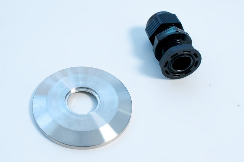
The feedthroughs used for the Ossila Glove Box are commonly known as Klein Flansche (KF) or Quick Flanges (QF). KF seals are one of the most economical vacuum port seals. They are made from stainless steel and are reusable – unlike CF flanges which form permanent seals. KF feedthroughs are made up of three parts: a clamp, a centering ring, and a blanking plate. These parts assemble to form a tight seal, held in place by a wingnut on a hinged swing clamp. The number used to describe KF seals (e.g., KF40) refers to the internal diameter of the welding plate. When choosing the correct seal for your system, you should choose the flange with a number matching the internal diameter of the borehole you wish to cover.
This table outlines the correct seal size for specific boreholes:
| KF Size | Inner Diameter (mm) | Outer Diameter (mm) |
| KF10 | 10 | 30 |
| KF16 | 16 | 30 |
| KF25 | 25 | 40 |
| KF40 | 40 | 55 |
| KF50 | 50 | 75 |
A cable gland is a device which forms a tight seal or indent around a cable. These can be positioned around a KF40 blanking plate with a bore hole. You can buy KF40 blank port covers, with different bore hole sizes. This, in combination with a cable gland, will allow you to feed a power source into your glove box.
Creating a Single Feedthrough Using Cable Gland
Creating an electrical feedthrough is easy and straight forward if you have the proper equipment. The simplest way to create an electrical feedthrough is using a cable gland and a blanking plate with bore hole. These are both cheap and readily available to source. The plate needs to be the appropriate size to cover your feedthrough port. For example, the our glove box uses the standard size KF40 port.
You also need to know your desired bore hole size before getting started, which will depend on the thickness of your wire. Cable thickness will also affect the cable gland size you need. When purchasing the cable gland, suppliers will quote a maximum and minimum cable diameter. Ensure that your desired cable lies within these boundaries, and that the main body of the cable gland will fit through the bore hole in your blanking plate.
We would recommend using a multi-socket extension lead as your power supply as this gives you maximum flexibility for using equipment in the main chamber.
You can create an electrical feedthrough in 7 easy steps:
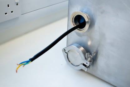
1. Remove the plug head from your power supply cable. Place your power source into the glove box through the window and run the cable through the port.

2. Unscrew the cap (or nut) from the cable gland. Then position the main body of the cable gland around the bore hole in the KF40 blank weld and fix onto the blanking plate.
3. Next, slide the blanking plate and cable gland along the cable, with the centering ring in between.


4. Check the desired position of the power source before you secure the cable gland. This will help you determine the length of cable needed inside and outside the chamber.

5. Screw the top nut onto the cable gland with the KF40 feedthrough positioned around the port. As you screw the cap onto the cable gland, it will begin to tighten around the cable. This will make a slight indent into the cable as it forms a tight seal around it.
6. Fix the KF blanking plate into place using the clamp and wingnut. Tighten by hand until this feels secure.


7. Lastly, rewire the plug. You now have a power supply within the glove box.
The combination of blanking plate, cable gland, and hinge clamp will quickly and easily provide a power supply to the glove box. It is a much cheaper method than bespoke design options. Following these steps will get you set up to conduct your experiments in inert conditions in no time at all!
Glove Box Feedthrough using Epoxy Resin
You can also create a personalized glove box feedthrough using a two-part epoxy resin and a KF40 female vacuum fitting adapter. Although these are not the prettiest feedthroughs, they allow you to have multiple cables through the same port. Epoxy resin offers another low-cost route.

To create this feedthrough:
- Use a clamp to suspend the adapter and feed the cables through. You will need to cover one side of the adapter fitting with a non-adhesive film or material. This should be tight enough to create a well in which you can pour the epoxy.
- Pour the epoxy in. You will need a thick layer of epoxy (roughly 1 cm should do), this should be enough to prevent diffusion of oxygen or moisture through the epoxy layer.
- Wait for it to set, then remove the protective material.
- Once you have done this, check for any cracks or pathways through the epoxy layer.


Glove Box