


Low Price Potentiostat for Cyclic Voltammetry and More
Available with electrochemical cell and electrodes for unbeatable value
Overview | Specifications | Gallery | Software | How to Set Up | Understanding Potentiostats
In the Box | Related Products | Resources and Support
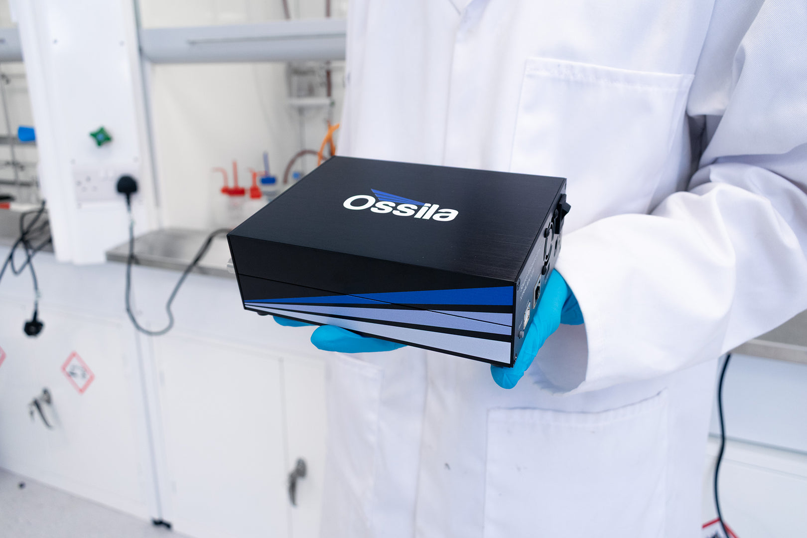
Perform linear sweep voltammetry, cyclic voltammetry, open circuit potential, and controlled potential electrolysis, with the powerful Ossila Potentiostat. You can be confident in your measurements with excellent applied potential and current measurement accuracy and a high applied potential and current measurement resolution.
Whether you are an experienced chemist and or a newcomer to the field, the easy-to-use PC software makes it straightforward for anyone to take accurate and precise measurements across a wide potential and current range. Set the relevant parameters then watch the measurement as it happens with live data plotting.
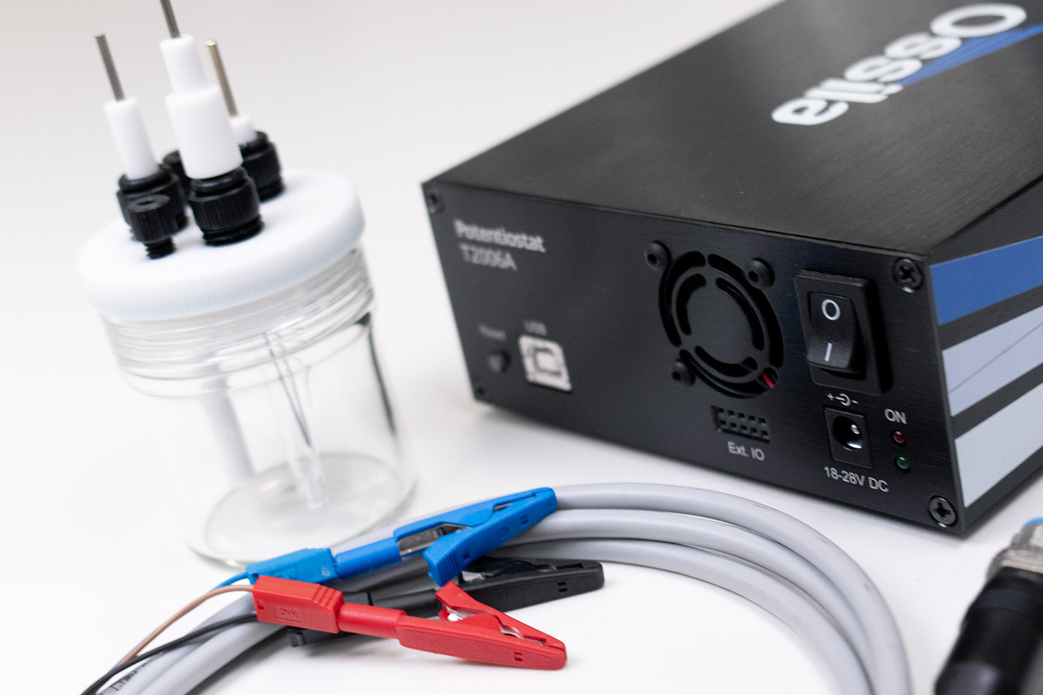
Buy as a standalone instrument to use with any electrochemical cell, or choose the complete kit which includes electrochemical glassware, your choice of non-aqueous Ag/Ag+ or aqueous Ag/AgCl reference electrode, a platinum disc reference electrode, and a platinum wire counter electrode.
Available as a Complete Kit
Add electrochemical cell & electrodes

Powerful Electronics
Potential range of ±7.5 V
Low Price Characterization
Cyclic voltammetry and more
Simple-to-Use Software
Free software for easy measurements
Key Specifications
| Potential Range | ±7.5 V |
|---|---|
| Potential Compliance | ±10 V |
| Applied Potential Accuracy | ±10 mV offset |
| Applied Potential Resolution | 333 µV |
| Scan Rate Range | 5 mV/s to 1000 mV/s |
| Maximum Current | ±200 mA |
| Current Ranges | ±20 μA to ±200 mA (5 ranges) |
| Current Measurement Accuracy | ±20 nA offset (at 20 μA range) |
| Current Measurement Resolution | 5 nA (at 20 μA range) |
| Communication | USB-B |
| Overall Dimensions (W x H x D) | 125 mm x 55 mm x 175 mm (4.91" x 2.17" x 6.89") |
| Weight | 600 g (1.32 lb) |

Understanding Current Specifications
Current is the key measurement parameter for the potentiostat. It it important to know the requirements regarding this essential measurement. The current measurement by a potentiostat must fall within the maximum current with specific accuracy and resolution assigned to specific current ranges.
Specification
Description
Maximum current
The highest electrical current that can be measured by a potentiostat for both positive and negative currents. If a measured current is outside of this range, a potentiostat will turn off the output potential to prevent damaging the unit.
Current ranges
To achieve a consistent level of accuracy and precision for current measurements at both milliamps and nanoamps, current measurements are split into a set of ranges. These ranges are typically separated by an order of magnitude, and whilst one range can usually measure the currents encompassed by the range below it, the accuracy and precision of the measurement will be worse.
Accuracy
The maximum amount that a measured current value can vary from the actual current value (scales with the order of magnitude of the current ranges). It is important to note that most measurements will vary by less than this amount.
Resolution
The smallest change in current that can be measured by a potentiostat. This value scales with the order of magnitude of the current ranges.
Understanding Voltage Specifications
Potential (voltage) is the key control parameter of a potentiostat. The range over which it can be swept, along with the precision, accuracy, and resolution of that control, are critical for acquiring meaningful electrochemical data.
Specification
Description
Potential range
The potential window that can be applied and measured by a potentiostat between the working and reference electrodes. This typically applies for both positive and negative potential, and in such a case is represented with a plus/minus symbol.
Potential compliance
The maximum limit for the potential that a potentiostat is capable of outputting between the working and counter electrodes. As with the potential range, it applies for both positive and negative potentials and as such is represented with a plus/minus symbol.
It is important to note the distinction between the potential range and the potential compliance. Potential range is the applied and measured potential between the working and reference electrodes, whilst the potential compliance is the absolute maximum potential that can be applied between the working and counter electrodes.
Accuracy
The maximum amount the output potential of a potentiostat can vary from the set potential (plus/minus offset). Specifically, this refers to the potential between the working and reference electrodes.
Resolution
As a potentiostat uses digital signals to determine the potential to output, any change in potential will appear as a step, and a scan profile a series of steps over time. The applied potential resolution determines how small these steps can be, as it is the smallest change in potential that can be output by a potentiostat.
Potentiostat Gallery
We're happy with the Ossila Potentiostat. We're currently using it in teaching labs to demonstrate basics of corrosion measurements. It is compact, easy to use, and affordable.
Branislav Dzurnak, Czech Technical University in Prague
Software
Easily perform linear sweep and cyclic voltammetry, open circuit potential, and controlled potential electrolysis. The maximum and minimum potentials can be defined along with the number of cycles, the scan rate, and the current range. Simply set the relevant settings and click 'Start', then watch the measurement as it happens with live data plotting.
Software updates are also provided at no extra charge and are available to download from our website.
As with all of our software, data is saved to .csv files so that you can analyze it with your favorite tool. The settings you define are saved alongside your measurement data so that you always have a record of your experimental parameters. Profiles allow you to save commonly used settings configurations so that you can quickly repeat measurements without re-configuring the potentiostat, further speeding up your research.
Software Requirements
| Operating System | Windows 11 (64-bit) |
|---|---|
| CPU | Dual Core 2.5 GHz |
| RAM | 4 GB |
| Available Hard Drive Space | 255 MB |
| Monitor Resolution | 1280 x 960 |
| Communication | USB 2.0 |
Getting Started with the Ossila Potentiostat
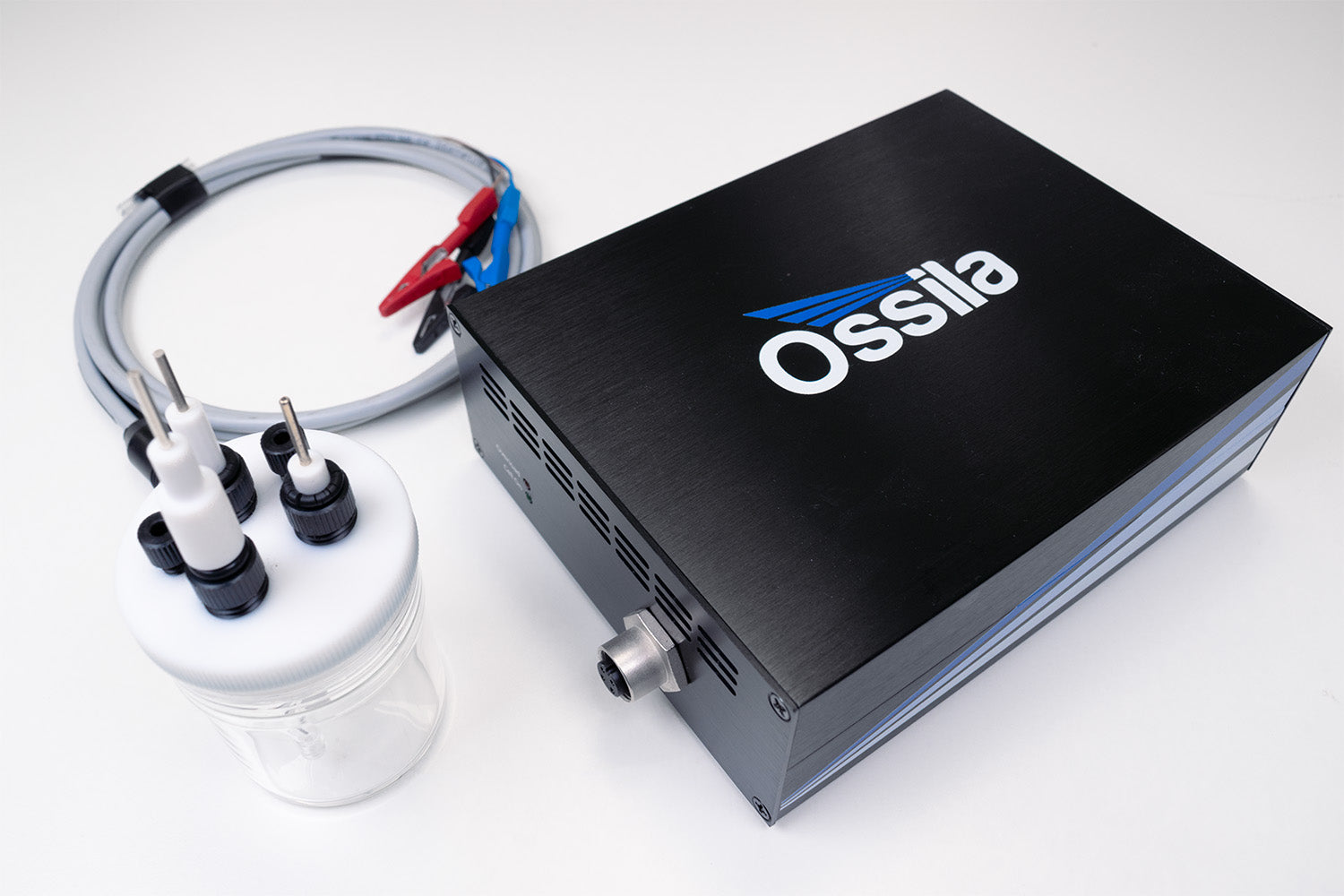
The Ossila Potentiostat has been designed to make it quick and easy to perform electrochemistry. Purchase the complete package to get everything you need to set up your three electrode system and enjoy a significant discount on the cell and electrodes.
Setting Up the Potentiostat
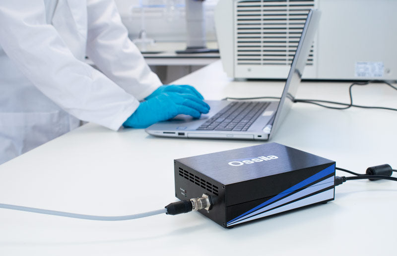
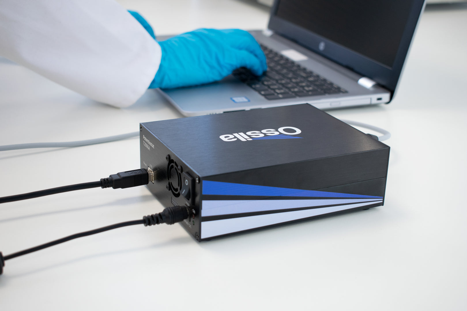
The Ossila Potentiostat is controlled by the (free to download and use) electrochemistry PC software. To get started, simply set up the physical aspects of your experiment and launch the software.
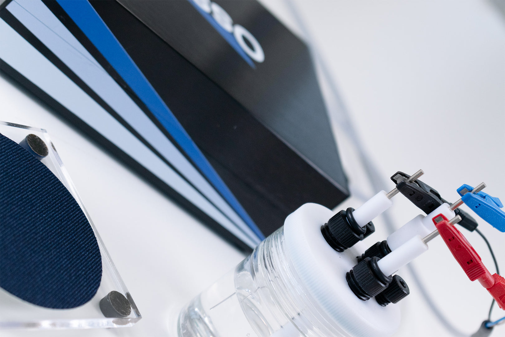
The experimental set up for cyclic voltammetry and other three electrode electrochemical methods consists of a potentiostat connected to a three electrode electrochemical cell containing the electrolyte solution. Once the electrodes have been placed in the cell, they can be connected to the socket on the front of the Ossila Potentiostat using the supplied cable and crocodile clips. The red clip connects to the working electrode, the black clip connects to the counter electrode, and the blue clip connects to the reference electrode.
Once you have set up your three electrode electrochemical cell and connected it to the potentiostat, taking an electrochemical measurement takes only a few clicks. The potentiostat will be detected automatically on starting the PC software, and from here the electrochemical method can be selected via the tabs at the top of the screen.
We also recommend switching on the potentiostat 30 minutes prior to use. This will allow it to warm up and reach a steady temperature, which will help to ensure a stable measurement.
Performing Cyclic Voltammetry with the Potentiostat
Performing cyclic voltammetry with the Ossila Potentiostat is quick and easy. The Ossila Electrochemistry PC software allows the maximum and minimum potentials to be defined along with the number of cycles, the scan rate, and the current range.
When you are ready to start the scan, click "Start" and watch in real time as the test is performed and a cyclic voltammogram is generated. The system will sweep the potential between the working electrode and reference electrode while measuring the current between the working electrode and counter electrode. This will be repeated for the specified number of cycles. If "Save After Measurement" is turned on, the measurement data and settings will be saved as CSV file once the sweep has finished.
Additional Specifications
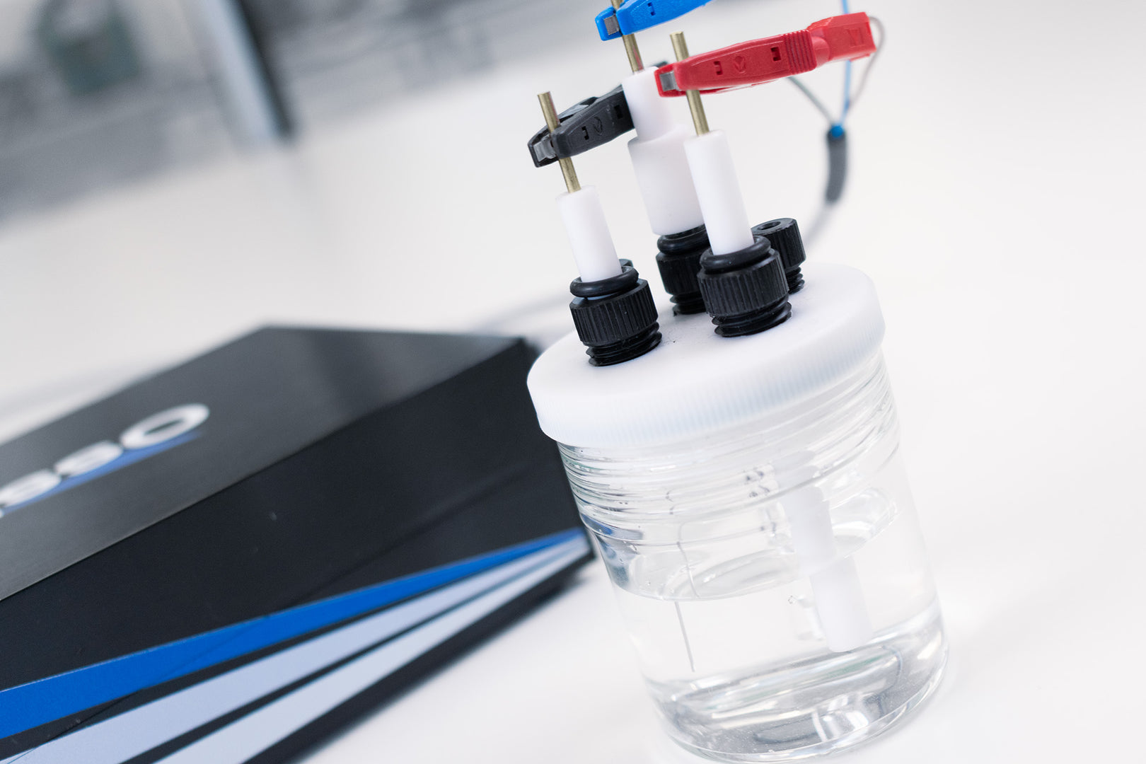
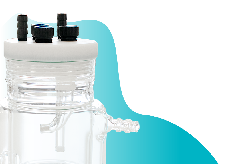
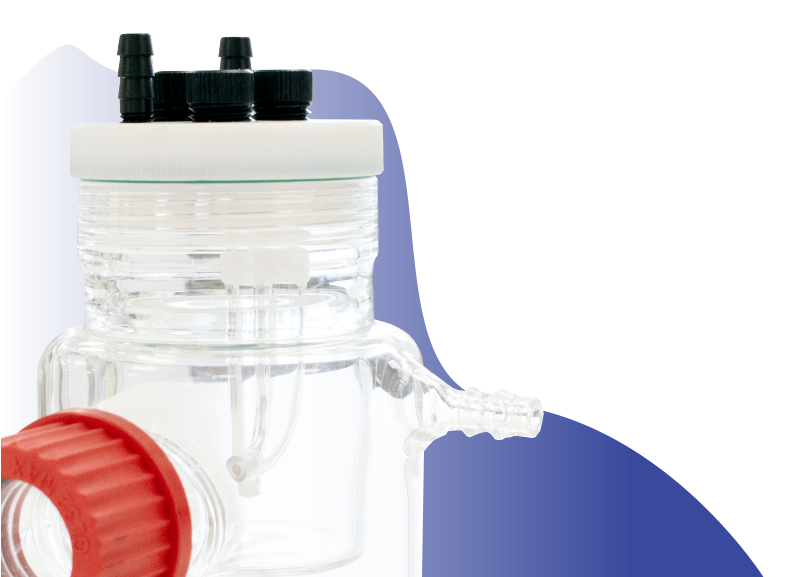
Standard Electrochemical Cell Glassware (Optional)
Screw-fit PTFE lid with three electrode holes and two gas holes.

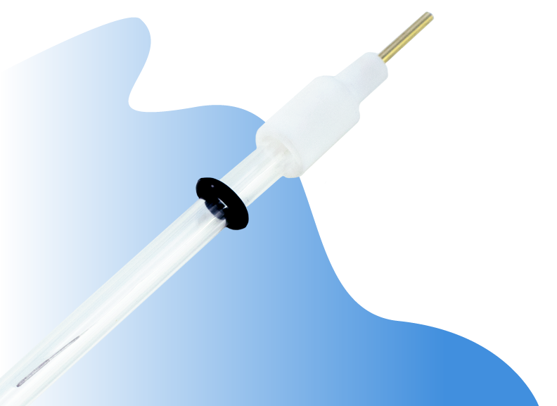
Platinum Disk Working Electrode (Optional)
Highly polished platinum embedded in polytetrafluoroethylene (PTFE) plastic bodies.
| Purity | 99.99% |
|---|---|
| Diameter | 2 mm |

Platinum Wire Counter Electrode (Optional)
| Purity | 99.99% |
|---|---|
| Diameter | 0.5 mm |

Non-aqueous Ag/Ag+ Reference Electrode (Optional)

Aqueous Ag/AgCl Reference Electrode (Optional)

User Manual
Understanding Potentiostats in Electrochemistry
Electrochemical techniques such as cyclic voltammetry, linear sweep voltammetry, and other types of voltammetry require a potentiostat to measure redox events taking place in a solution.

A typical electrochemical experimental set up consists of a potentiostat connected to a three-electrode cell via:
- working electrode
- counter electrode
- reference electrode
Analysis of the data recorded by a potentiostat reveals various intrinsic electrochemical properties of the material, depending which method is used. Using techniques like cyclic voltammetry, potentiostats can be used to find the redox potential of materials, determine the reversibility of a reaction, provide a quantitative description of electrochemical reversibility, and determine the energy levels of semiconducting polymers.
How Does a Potentiostat Work?
A potentiostat controls the potential difference between two electrodes and measures the resulting current flow. It is able to vary its output potential (voltage) in response to changes in the resistance across a circuit. In electrochemistry experiments, potentiostats are able to supply more or less current so that the potential across an electrochemically active cell remains constant as per Ohm’s Law: voltage (V) = current (I) x resistance (R).
A potential is applied to the working electrode, which is held at a defined voltage relative to the reference electrode. The surface of the working electrode is the primary area of interest because, under an applied potential, the number of electrons at its surface changes (increases or decreases). The applied potential alters the electrochemical potential of the working electrode, making oxidation or reduction thermodynamically favorable. This drives the exchange of electrons between the electrode and species in the electrolyte. The specifics of this electron exchange depends on the chemical system under investigation.
The measured current is the exchange of electrons per time at the electrodes surface. The current flows between the working electrode and counter electrode (in a three electrode set up). Measuring current as a function of potential helps identify the point at which electron transfer is most efficient. This reveals key information about redox behavior, analyte concentration, and electrode performance. These characteristics are key to understanding and optimizing electrochemical reactions.
Electrochemical Methods
The Ossila Potentiostat and Electrochemistry Software make it easy to perform the most commonly used electrochemical methods.
Cyclic Voltammetry
One of the most useful and commonly used electrochemical techniques. In cyclic voltammetry, a linearly ramping potential is applied between the working and reference electrodes. This potential is cycled such that the ramp is applied in one direction, then in reverse, forming a triangular wave. The electrical current is measured between the working and counter electrodes to produce a cyclic voltammogram.
Linear Sweep Voltammetry
Linear sweep voltammetry is an electrochemical method in which the potential is linearly swept in one direction from the lower potential limit to the upper potential limit. Linear sweep voltammetry is useful for irreversible systems and can be used to calculate the peak current, the peak current potential, and the half-peak current potential.

Controlled Potential Electrolysis
Three electrode controlled potential electrolysis is a type of bulk electrolysis (or potentiostatic coulometry) in which the potential between the working and reference electrodes is kept constant while the current through the cell is measured. As the analyte is reduced or oxidized, the measured current will approach zero.
Open Circuit Potential
Open circuit potential is an electrolytic method that can be used to measure the resting potential of an electrochemical cell between the reference and working electrodes. Systems that are in equilibrium over the timescale of the experiment will have a constant open circuit potential.
Applications of Cyclic Voltammetry
Cyclic voltammetry reveals a number of important electrochemical properties about the material being investigated, including:
- Redox potentials. The reduction and oxidation potentials of a material describe how readily it gains or loses electrons. Reduction occurs when a chemical gains electron(s), and oxidation is when a chemical loses electron(s). Redox potential is an intrinsic property of materials.
- The reversibility of a reaction. How reversible a given electrochemical reaction is. For a completely reversible reaction, the concentration of oxidized species and reduced species should be in equilibrium.
- Electron transfer kinetics. A quantitative description of electrochemical reversibility; how fast or slow the transfer of electrons is in a reaction. For a reaction to be reversible, electron transfer must be sufficiently fast.
- Energy levels of semiconducting polymers. The energy levels of semiconducting materials. This is particularly useful for photovoltaic applications as it provides an estimate for the energy of the highest occupied (HOMO) and lowest unoccupied molecular orbitals (LUMO).
Electrochemical Cell Set-Up
Potentiostats can be used to control two, three or four electrode configurations (and as discussed above, multi-channel bipotentiostats or polypotentiostats can control rotating ring-disk electrode systems).
The three electrode set-up is by far the most common and consists of a working electrode, a counter electrode, and a reference electrode. Each of these three functions also exists in a two electrode cell, only a single interface both provides a reference potential and allows current to flow across the cell. The primary issue with such a set-up is that it renders it impossible to accurately control the potential at the working electrode.

Working electrode
The working electrode is the primary electrode in an electrochemical system. It is where the applied voltage enters the system, and where most electrochemical reactions and electron transfer take place. Measurements of potential and current in an electrochemical system involve the working electrode for both two and three-electrode systems.

Reference electrode
By having a stable, known, and well-defined electrochemical potential, reference electrodes provide a constant for an electrochemical measurement. In an ideal electrochemical system, zero current will flow through the reference electrode, enabling accurate measurements and control of the potential at the working electrode. This is achieved by the reference electrode having a very low impedance, ideally zero.

Counter electrode
Counter electrodes, also known as auxiliary electrodes, complete the circuit of a two or three-electrode system. In two-electrode systems, the counter electrode is also used as the reference electrode. In three-electrode systems, the current is measured between the working and counter electrodes.
In the Box
- Potentiostat
- Shielded cable and crocodile clips
- Test cell chip
- USB-B cable
- 24 VDC power adapter
- USB Driver with QC test data
Included in complete kit:
- Standard electrochemical cell*
- Platinum disc working electrode*
- Platinum wire counter electrode*
- Non-aqueous Ag/Ag+ or aqueous Ag/AgCl reference electrode*
* Available to be purchased separately
Accessories and Related Products
Resources
 How to Perform Cyclic Voltammetry on a Polymer
Learn how to perform CV measurements with the Ossila potentiostat.
Read more...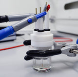 Troubleshooting Cyclic Voltammetry
Problems with cyclic voltammetry are often caused by relatively small mistakes. There are several different ways to troubleshoot the issues, depending on the problem.
Read more...