


How to Measure Absorbance

Using Spectrophotometers and Spectrofluorometers | Using Modular Spectrometers
Converting Transmittance | Taking Absorbance Measurements | Measurement Tips
In an absorbance measurement, a sample is exposed to a broadband light source and a spectrometer measures the light that is transmitted through it. Using these transmittance measurements, you can calculate relative absorbance at different wavelengths.
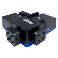
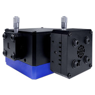
Absorbance measurements can be taken with modular spectrometers, like the Ossila USB Spectrometer, that use array detectors to measure the entire spectrum simultaneously. These need to be combined with an external light source usually aligned on an optical breadboard. Alternatively, spectrophotometers and spectrofluorometers use a monochromator, single pixel detector, and broadband light source within one enclosed system. These larger systems can measure absorbance with higher sensitivity and improved resolution.
Absorbance Measurement Equipment

Measuring Absorbance with Spectrophotometers
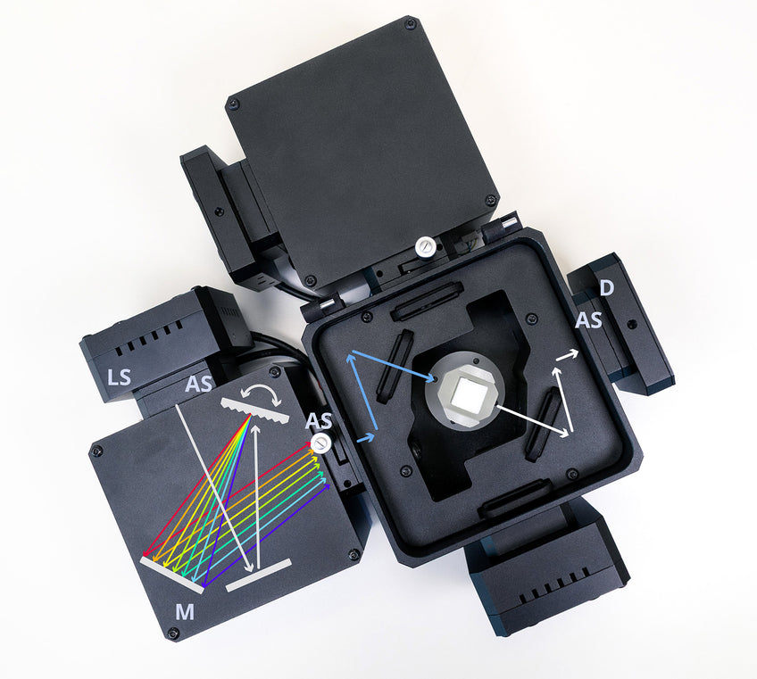
With a standalone system, all the necessary components are encased in one unit. These units contain:
-
A Broadband LED light source
-
Adjustable Slits
-
A Sample Holder
-
A Monochromator
This splits the broadband light source into its constituent wavelengths. A rotating diffraction grating directs different portions of the dispersed light towards the variable exit slit. In an absorbance measurement, the monochromator systematically moves through the wavelength range, allowing the detector to measure transmitted intensity at each wavelength.
-
A Single Pixel Detector
As individual wavelengths are selected by the monochromator, spectrofluorometers and spectrophotometers can use a single pixel detector to measure intensity, unlike modular spectrometers. With single pixel detectors, light intensity for each data point is captured over a larger area, so spectrofluorometers can measure absorbance measurements with higher sensitivity and precision.
This diagram shows the path of light travelling through a spectrofluorometer during absorbance measurements. this shows the various components involved including a monochromator (M), adjustable slits (AS), a light source (LS) and detector (D).
Measuring Absorbance with USB Spectrometers
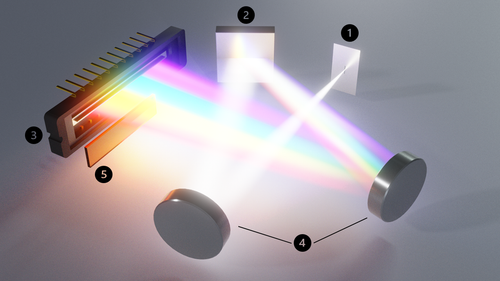
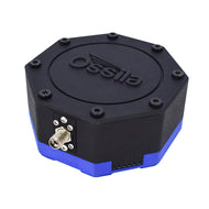
With a modular system, like the USB Spectrometer Kit, the spectrometer contains some kind of dispersion element (usually a diffraction grating) and a charge-coupled device (CCD) array detector. The light from the incoming signal is dispersed within the spectrometer, and the intensity of each wavelength is measured simultaneously.
The diagram shows the light path through a USB spectrometer via: (1) the entrance slit, (2) diffraction grating, (3) detector, (4) optics and mirrors & (5) high order filters.
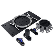
You need to combine this type of spectrometer with an external light source and sample holder, and align these elements to allow light to travel straight through your sample into the spectrometer.
To do this, you can align the components on an optical breadboard. You will need to take care to reduce background light as much as possible if using this approach.
Alternatively, you could use optical fibers to direct the light. Using optical fibers will reduce the amount of stray light that can enter your spectrometer, and can help with low signal measurements.
Converting Transmittance to Absorbance
Transmittance (T) is a measure of how much light passes through a sample. It's determined by the ratio of the intensity of light entering the sample (I0) to the intensity of light exiting the sample (I):

You can calculate the absorbance spectrum, A, of the sample by taking the base 10 logarithm of the transmission spectrum:

From the equation above, you can calculate the absorbance of a sample by first calculating the transmission, and then simply taking the negative logarithm. The factor of 0.43 comes from taking the base-10 logarithm of the transmission rather than the natural logarithm. In some scientific fields, the absorbance is defined by the natural logarithm of the transmission. Within the study of liquids and solids, you would generally use the base-10 logarithm.
The table below shows the relationships between different values of transmission and absorbance.
| Transmission | Absorbance |
|---|---|
| 0.01 | 2 |
| 0.02 | 1.7 |
| 0.05 | 1.3 |
| 0.1 | 1 |
| 0.2 | 0.7 |
| 0.5 | 0.3 |
| 1 | 0 |
Absorbance can be measured directly using the Ossila USB Spectrometer by selecting the "Absorption" setting. The software will require a background measurement and a direct beam measurement be taken, then you can measure the absorption.
Taking Absorbance Measurements
Recording an absorbance spectrum requires you to measure three separate spectra. These are:
1. A background spectrum
The detector in the spectrometer will record a signal even when there is no light falling on it. This is due to the thermal generation of electron-hole pairs, which produce a "dark" signal. Because this background is unrelated to the sample, you will need to subtract it from all subsequent spectra in order to account for these effects. You can take a background spectrum by turning off the illumination source and recording a spectrum.

2. A reference spectrum, I0
This spectrum will measure how much light is incident on the sample. You can do this by turning on our illumination source and recording a spectrum without the sample present.
It is often necessary to use a reference sample in place of your actual sample. For example, if you are interested in the transmission of a thin film that is deposited on a glass substrate, you should place a blank glass substrate in the light path for the reference measurement. This will account for any optical effects.
If you are measuring the transmission of molecules in solution inside a cuvette, you should exclude the optical properties of both the solvent and the cuvette. In this case, use a cuvette containing just the solvent as the reference sample. The background should be subtracted from the measured spectrum.
3. A measurement spectrum, I
Once you have measured the background and reference spectra, place the sample in the light path and then take the measurement spectrum. You should then subtract the background from this spectrum.

If you select the 'Absorption' measurement type in Spectroscopy Software, this background subtraction and the conversion from transmission to absorbance spectra happens automatically. This allows you to easily get an absorbance spectra.

Tips for Absorbance Measurements
Loss of Light
When calculating absorbance from transmission, you must assume no light is reflected from the sample surface and no light is scattered by the sample. These additional loss mechanisms prevent light from passing through the sample, so you must reduce these effects as much as possible.
This technique is not appropriate for measuring the absorption through turbid/rough media where high scattering losses are expected, or of media/solutions with a high refractive index where significant reflection can occur at the interface with air.
Reducing Noise
Transmission and absorption measurements are particularly susceptible to noise. Each of the three spectra involved in the calculation will have its own associated noise, which will be added when the calculations are completed. There are some approaches to help you reduce noise and achieve a clean transmission or absorption spectrum.
- Choose the right light source. You should ensure a high intensity of light over the wavelength range being measured.
- Use the correct integration time. To maximize the signal, you should use an integration time that gives a clear signal for the reference spectrum. Ideally, the maximum point on the reference curve should reach 90% of the spectrometer's saturation values. If you use a high intensity light source, you'll be able to use shorter integration times.
- Use spectral averaging. By averaging several spectra, you can reduce the noise in the average spectrum by the square root of the number of samples. We recommend that you use a bright source, as this means you can have short integration times and, therefore, many spectra can be recorded and averaged quickly.
- Be aware of limitations and prepare the sample accordingly. If you have a highly absorbent sample, almost no light will be able to pass through. This leads to a similar results as using a dim light source, i.e., there will be no signal (or the signal will be obscured by noise). Ideally, you want the transmission of the sample to remain above 0.05 for all wavelengths (i.e., the absorption is below 1.3). Practically, you can achieve this by reducing the concentration of molecules in your solution or reducing your film thickness. If your spectra shows very high absorption, it may not be accurate.
Spectroscopy Equipment & Components
Learn More
 How To Read An Absorbance Spectrum
There are many material properties and phenomena that can be measured with absorbance spectroscopy. The key to unlocking these insights lies in carefully reading absorbance spectra and interpreting spectral properties they reveal.
Read more... Negative Absorbance: Can Absorbance Ever Be Negative?
In general, you should not be measuring negative absorbance values for any sample.
Read more...References
- Rocha, F. S., Gomes, A. J., Lunardi, C. N., Kaliaguine, S., & Patience, G. S. (2018). Experimental methods in chemical engineering: Ultraviolet visible spectroscopy-UV-vis. The Canadian Journal of Chemical Engineering, 96(12), 2512–2517. DOI:10.1002/cjce.23344
- Hestand, N. J., & Spano, F. C. (2018). Expanded theory of H- and J-molecular aggregates: The effects of vibronic coupling and intermolecular charge transfer. Chemical Reviews, 118(15), 7069–7163. DOI: 10.1021/acs.chemrev.7b00581
- Makuła, P., Pacia, M., & Macyk, W. (2018). How to correctly determine the band gap energy of modified semiconductor photocatalysts based on UV–vis spectra. The Journal of Physical Chemistry Letters, 9(23), 6814–6817. DOI: 10.1021/acs.jpclett.8b02892