How do Syringe Pumps Work?
A syringe pump is an electromechanical device that are designed to convert rotational motion into linear motion. This linear motion is then used to drive the plunger of a syringe and deliver a precise amount of solution. Understanding the design and operation of syringe pumps will help inform you on what specifications are important for your application and what is achievable using your experimental setup. This will also help you understand what sources of errors may arise due to the design of your system.
The rotational motion used by the syringe pump gets delivered via a stepper motor, which is precisely controlled by driver electronics. Through clever use of sophisticated microcontrollers and driver technology, the rotation of the lead screw can be done in extremely small, discrete steps. This results in a minute linear motion of the plunger as small volumes of your solution are dispensed.
The mechanics of the syringe pump are designed to ensure minimal frictional losses and keep backlash to a minimum. This ensures that all rotational motion is converted to linear motion and that the torque generated by the motor is used to displace fluids rather than overcome frictional forces within the pump.
Although modern syringe pumps are capable of moving miniscule distances, most solutions will not be able to take advantage of these small distances. For viscous materials or high flow rates, the pressure required to move the fluid requires a large force. If the torque generated is not high enough, the motor will stall (often called missing steps), and the syringe will not dispense.
To fully understand how a syringe pump works, you must understand the mechanics involved in the movement of the plunger. It is also essential to grasp how the design of the mechanical fixings works together with the electronic control circuitry to deliver precision movement. It is this precision movement that results in the accurate and consistent dispensing of your solutions.
Displacement of Fluid in the Syringe
Syringe pumps work on the simple premise of displacement. This occurs when movement of the plunger results in the displacement of fluid within the syringe. You can then direct this fluid (via tubing) towards where you want to deliver it. The rate at which fluid is pumped out of the syringe is related to the rate at which the plunger is compressed. Similarly, the volume dispensed is related to the distance moved by the plunger.
Figure 1. shows the basic structure of a syringe, consisting of a barrel and a plunger. The barrel holds the solution, while the plunger displaces it by reducing the volume of the barrel. Each syringe also has a flange. This makes them easier to handle and also allows for mounting on the pump. The end of the syringe is terminated with a Luer Lock, allowing for the connection of tubing.
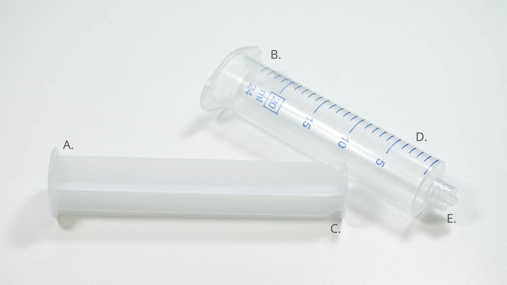
You can calculate the volume displaced by the syringe by taking the internal diameter and using it to work out the cross-sectional area. Once you have the measurement of your cross-sectional area, you should multiply this by the distance that the plunger has moved. This will yield the total volume of fluids moved by the pump. You can use a similar calculation to work out the rate of solution that is dispensed. Do this by multiplying your cross-sectional area by the rate of movement of the plunger. This will give you the dispense rate of the pump.
What Moves the Syringe?
In a syringe pump, the motor plunger is moved by a central block that is flush against the plunger’s flange. The flange on some syringe pumps can be connected to the block via a clamping mechanism. This allows the central block to not only control the dispensing of solutions but also the withdrawal of solutions.
It is the rotation of the motor that causes movement of the central block. Here, rotational motion from the motor is converted to the linear motion of the block. This is achieved using a lead screw and nut combination. Most syringe pumps will use a stepper motor, which moves the motor in a series of discrete steps, while the timing of these steps is controlled by the driver electronics within the system.
Each part described here can impact the performance of the syringe pump. There are several factors you must consider when assessing the effectiveness of your syringe. These include the design of the central block, the type of screw being used, the connection between the screw and the motor, the type of stepper motor being used, the electronics used to drive the motor, and the software that controls the driver.
The entire system of a syringe is a combination of mechanical design and electronics. The stepper motor, therefore, acts as the interface between the two.
Mechanics of a Syringe Pump
Figure 2 shows the main mechanics behind the syringe pump. Central to this mechanical design is the lead screw, which is supported at both the start and end of the block's travel. This support consists of a bearing, which allows the lead screw to be fixed while minimizing friction. The screw itself sits freely in the bearing. Locking collars are used to ensure that the screw can only rotate and not move backwards and forwards. These are situated either side of the bearing housing.

At the motor end, the lead screw can be connected to the motor in one of two configurations. These are via a coupling or via a drive belt. A coupling involves a rigid connector between the motor and lead screw, where one end of the coupling is clamped onto the lead screw and the other end is clamped to the motor's shaft. The rotation of the motor relates to the rotation of the screw. Belt-driven systems use a combination of gears and belts to transfer rotational motion and torque from the stepper motor to the lead screw.
Both belts and couplings have their advantages and disadvantages. Couplings have a low loss of torque and no backlash; however, the alignment of the shaft and lead screw is critical, and the configuration also takes up more space. Belt-driven systems can accommodate shaft misalignment, dampen vibrations, and be used to easily reduce gearing; however, backlash and wear can occur.
A nut is used to convert the rotational motion of the lead screw to the linear motion of the moving block. The central block also has a guide, which will be in the form of a linear rail or single or dual linear rods. When the lead screw rotates, the teeth of the screw will engage with the teeth of the nut, causing it to move. These guides are necessary as they constrain both the carriage and the nut, stopping any rotational movement. They do this by ensuring that the teeth of the nut engage with those of the screw so that it moves along the length of the screw instead of rotating in place.
For each rotation of the screw, the distance that the central block will move is based upon the pitch of the lead screw as well as the total number of threads (sometimes known as starts). The pitch of a lead screw is another name for the distance between adjacent threads. By multiplying this pitch with the number of starts, you can obtain the linear distance of one whole rotation. For example, a four start lead screw with a 2 mm pitch would result in 8 mm moved during each rotation of the lead screw.
Stepper Motors and Movement
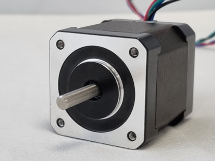
The stepper motor is what provides the rotational movement to the lead screw, the movement of the plunger, and the dispensing of the liquid. Figure 4 shows a simplified diagram of the internal mechanism of a stepper motor. The general principle is quite simple: the central shaft of the motor (known as the rotor) includes a permanent magnet, and a series of stators are arranged in a ring around the outside of the shaft. These are electromagnets that can be selectively magnetised to attract or repel the magnet on the shaft.
Pairs of these stators act together, attracting the rotor magnet, aligning it with the stator, and thus rotating the shaft. The angular distance between each stator is the minimum distance that the motor can rotate. This is referred to as a step. In this simplified design, there are four pairs of stators, which means that the minimum distance that can be rotated will be 45⁰. This is significantly larger than the standard 1.8⁰ or 0.9⁰ step values of most stepper motors.

To improve the resolution of stepping, modern stepper motors use a hybrid design. In this design, the rotor and stator have teeth with equal angular spacing between them. In the first stator pair, these teeth align exactly with the teeth of the rotor. The next set of stators is offset by an angle equal to a quarter of the distance between the teeth. This repeats for each pair. The rotor itself consists of a permanent magnet formed as two discs, one of which forms the south magnetic pole and the other the northern pole. The teeth on these discs are offset from one another by half the tooth distance.
To rotate the motor, the poles are energised in sets. These sets typically consist of four stators, arranged into two pairs. For example, an 8-pole stepper motor will have an A and a B set of stators. Two stators in each set will be wound clockwise (A and B stators), and two will be wound anti-clockwise (A' and B'). The stators in a pair are set opposite each other, while the pairs in the set are perpendicular to each other. When the set is energised, this results in the two pairs within a set acting as opposing poles.
When energising occurs, the rotor teeth align with the stator teeth. By alternating which set is energised and which direction of current is passed through, the polarity of the stators can be in one of four different configurations.
To rotate the rotor by a whole tooth requires four discrete steps. Therefore, for a rotor with 50 teeth, this will result in 200 discrete steps per full revolution. In order for the rotor to move by a quarter of the angular distance between the teeth, each pair must be energised in turn, while the quarter angular offset must be utilised for each pair.
Most stepper motors use a total of eight stators arranged in four pairs. Each of these stators will also have six teeth. This gives an average total of 48 teeth. The rotor, however, will have 50 teeth. This means that each time the stators are energised, the rotor will move one 200th of a full rotation. This is an angle of 1.8⁰. In a motor with 0.9⁰ stepping angles, there are 16 stators arranged in eight pairs. Therefore, there will be a total of 96 teeth on the stators, while the rotor consists of 100 individual teeth.
If we use the example of an 8mm lead screw, for a step rotation of 1.8⁰, each step will result in a movement of 0.04 mm. This is much larger than the minimum distance that most stepper motors can move. While the stepper motor movement discussed here has all been about individual steps, it is possible to break these steps up by slightly changing how the stators are energised. This results in the ability to do something called micro stepping.
Motor Control and Micro Stepping
Control of the motor is achieved using a simple circuit called a driver, which works by controlling the timing and polarity of electrical pulses sent to the motor. By alternating which set is energised, as well as the direction of the current, the driver rotates the motor. By setting the time between the energising of the stators, it controls the rate at which the motor rotates.
One thing that sets stepper motor drivers apart, however, is that they allow the motor to move fractions of an angle. They do this simply by varying how energised each set of stators is. This is called micro stepping. As the name implies, this technique allows the motor to move a small fraction of a step. This reduction in stepping size typically occurs on a binary scale, with most values being either 1/32 or 1/64. Some, however, can go as low as 1/256. This value means the driver can divide each individual 1.8⁰ step into 32, 64, or even 256 smaller steps. This could give you an individual step angle as small as 0.007⁰.
Micro stepping is done by energising both sets of stators simultaneously. In Figure 6, we use a simplified view of a stepper motor to show how micro stepping works. To achieve the lowest level of micro stepping (1/2), the driver simply energises the two sets an equal amount. This results in the rotor being equally attracted to both sets of stators, and an equilibrium position is reached halfway between the current position and the next position.
Things are a little more complex when higher levels of micro stepping are involved. To go these shorter distances, the driver must control which pair is energised as well as the current direction. In these cases, however, it must also control the strength of the magnetic field generated by the stators.
As the motor is controlled digitally, the stator is only in an on or off state. To overcome this, a digital system can use pulse-width modulation to reduce the average power delivered. For this, the stators are powered on for a percentage of time within a given period. This is known as the duty cycle. If a stator is always turned on, the duty cycle is 100%. If it’s turned off, it is 0%, and if it’s on for half the time, it is 50%.

Figure 7 shows how the duty cycle for the stator sets A and B will vary over a single step when using a micro stepping measurement of 1/64. By reducing the duty cycle, a lower-strength magnetic field is used to move the rotor. As a result, when it does a single micro step, the motor generates less torque. For 1/64 micro stepping, the torque generated per micro step is less than 2.5% of the maximum torque. By increasing the number of micro steps per discreet movement, the torque can be increased. The inlet on Figure 7 shows how the increase in the number of micro steps taken results in an increase in torque.
Because the torque produced by the motor determines how much force is applied to the syringe, there will be a lower maximum force applied when micro stepping occurs. This can be an issue in some applications, specifically when either high flow rates, high viscosity, or constrained flow channels are used. The reason for this is that a higher pressure is required to move fluids in these conditions, and so a higher torque is required to push the syringe. If the torque is not high enough, the motor can stall and not move. This will result in inaccurate dispensing rates and volumes.
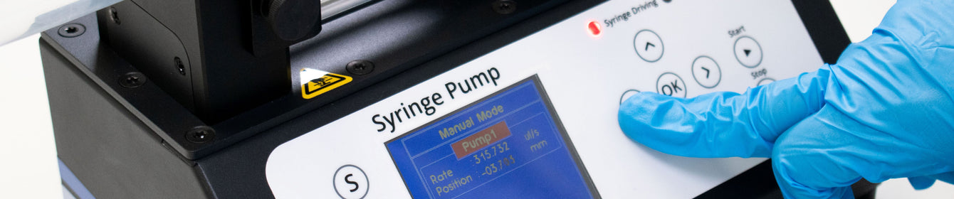
Syringe Pump
Further Resources
 Peristaltic Pumps: How Do They Work?
Peristaltic pumps are a type of positive displacement pump that use the progressive compression and relaxation of a flexible tube to move fluid along. These pumps mirror the biological process called peristalsis. This is where the rhythmic contraction of muscles is used to transport fluid through the body, such as in the digestive tract.
Read more... Getting Started With a Laboratory Syringe Pump
A syringe pump is an indispensable tool for accurately controlling the delivery of fluids. They are used in a wide range of applications, from chemical and biological research to medical and industrial settings. These versatile devices are used for tasks such as reagent addition, sample injection, continuous infusion, and more. Understanding the fundamentals of syringe pumps is essential for their effective use, maintenance, and troubleshooting.
Read more...