Reinventing the Spin Coater Chuck: Fluid Dynamics Simulations
At Ossila, we continually allocate resources for improving our existing products. We want to consistently boost product efficiency and increase available features. This includes our corner-stone product - the Ossila Spin Coater.
We have drastically redesigned our vacuum-free spin coater chuck, aided by fluid dynamics simulations performed by our R&D team.
Why Is Chuck Design Important?
The spin coater chuck’s design plays a vital role in effective thin film coating. Chuck design impacts many things including:
- Acceleration Speed - Heavier chuck designs increase the chuck inertia, slowing the responsiveness of the motor. This can limit acceleration and deceleration speeds - the same way it is much harder to stop a car in motion than a bicycle.
- Maximum Achievable Speeds - Designs with poor aerodynamic performance introduce drag reducing the maximum achievable speed.
- Rotational Vibrations - If a chuck's center of mass is off axis, this can introduce instability in the rotation, resulting in unwanted vibrations. These vibrations reduce coating uniformity.
- Air Flow - The position of the substrate and the depth within the recess determine the uniformity of airflow across the surface. The chuck design can help drive smooth airflow across the substrate, increasing film uniformity.
- Presence of Solvent Vapors - Any solvent vapors present in the bowl reduces the effective evaporation rate. The chuck design can help drive airflow out of the bowl, reducing stagnant pockets of air and solvent build-up.
Multiple Substrate Sizes with the New Ossila Spin Coater Chuck
The bigger, better chuck provides an all-in-one solution if you have multiple sizes of substrates to coat. The new spin coater chuck has multiple recesses of different depths, fitting many of our substrates. The new design fits:
- 20 mm x 15 mm substrates
- 25 mm x 25 mm substrates
- 25 mm x 75 mm microscope slides
This means that you can coat many different substrate sizes without having to change chucks. Additionally, the new spin coater chuck has a new shape. This will make installing, removing or replacing the chuck as easy as possible.

Controlled Air Flow with the New Ossila Spin Coater Chuck
Air primarily enters the spin coater through the hole on the lid, through which it forms a fast-moving column of air directed towards the substrate. This column of air aids drying along with evaporation/vaporization of solvent. This airflow carries away the solvent vapors. It also forms a region of increased pressure directly over the substrate which helps to pin the substrate to the bottom of the recess. This is one of the reasons the Ossila Spin Coater works so well without a vacuum pump system.
The mixture of air and solvent vapor then continue to the wall of the spin coater where it eventually vents through the gap between the lid and the frame. Any air that is present beneath the chuck is also drawn along with the fast-moving column of air leaving the spin coater bowl. The new design has a few cleverly thought-out features to manipulate these air flows and improve your coated films:
- Deflecting solvent vapors upwards -The chuck has a ‘lip’ which diverts most of the solvent vapors and air upwards along the walls of the spin coater to vent out through the gaps. This reduces the interaction between potentially harmful solvents and elements of the spin coater while also maintaining a clean and contaminant-free environment.
- Minimizing stagnant pockets of air - Low velocity regions of air collect vapors from the coating processes over time. The new chuck has an improved design which eliminates all of these regions, thus preventing potential corrosion, cross contamination and extends the lifespan of the motor components.
- Optimized Airflow Uniformity - Our studies allowed us to optimize the optimal recess depth, lid hole diameter and the gap between the lid and spin coater, to maximize air flow uniformity across the substrates surface. This will further improve coated film uniformity.
How the Chuck Design Improves Mechanical Performance
Not only have we looked are the aerodynamics of the chuck design we have looked at the mechanical performance of the system as a whole and worked to integrate new design changes that will improve this. As mentioned previously the minimum and maximum achievable speed as well as the maximum achievable acceleration are all impacted by the physical design of the chuck. To do this, we have:
- Increased Area, Reduced Overall Mass - While the diameter has increased by 23%, we have avoided the expected increase in volume. We have eliminated the large rim underneath the chuck, while improving stability using the new rounded rim design. We have also moved from a flat bottom to a gradient, trimming off excess material. The new unique design minimizes the amount of material used near the edges and proportionally maximizes the material towards the center. This neatly leads to our next reason why our spin coater chuck is so good.
- Increased Rotational Stability - Since our chucks have more mass towards the center, the chuck has a low moment of inertia whilst also providing the structural support necessary for larger substrates. Therefore, our motors can spin the chuck at much lower energies compared to the previous chuck designs. This allows the new spin coater to achieve higher speeds. This reduces the impact of stray forces on the rotational speed of the chuck.
Fluid Dynamics Simulations: Old vs. New Spin Coater Chuck
Fluid dynamics simulations were instrumental in designing the new spin coater chuck. These allowed us to study air flow patterns within the spin coater.
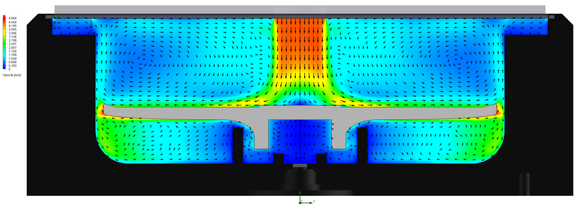
With the previous spin coater chuck design, you can see a swift drop off of air down the sides of the chuck. This air is directed towards the underside of the chuck where it is more likely to get trapped. This can increase the likelihood of stagnant regions of air solvent build up.
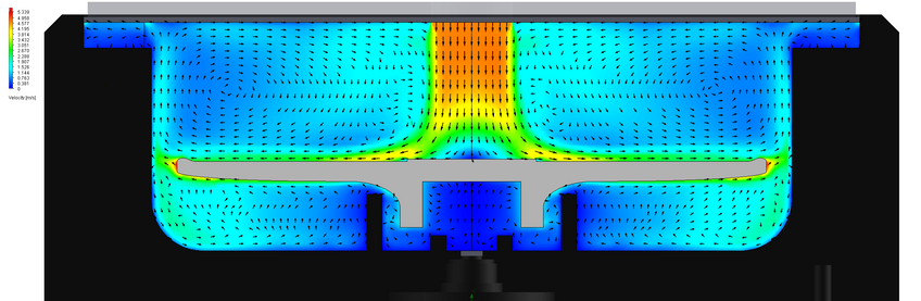
With the new spin coater chuck design, you can see that air at the edge of the chuck is directed upwards, assisting its escape from the spin coater bowl. You will also notice this air flow is a lot faster and smoother using the new design.
Contributing Authors
Written by
Mechanical Engineer
Edited by
Product Developer