Installing Your Glove Box
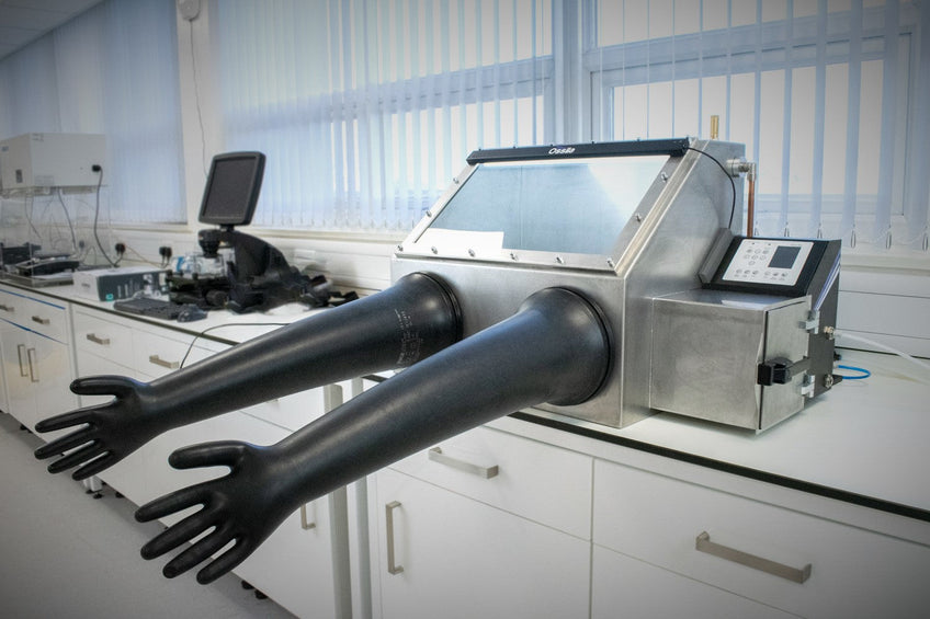
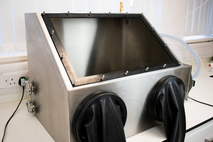
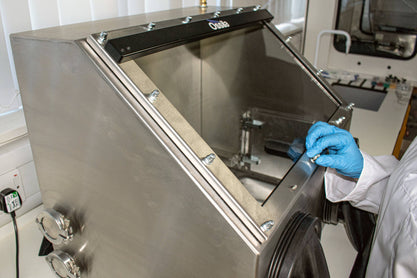
We designed the Ossila Glove Box to be easy to install and maintain. Its benchtop design, small footprint, and quick set up means that it is suitable for laboratories. It also means that the system is portable, so you can transfer it between labs if needed.
To set up your glove box:
- Install the moisture and oxygen sensor boards
- Secure the gloves on the glove ports
- Assemble the window, taking care to ensure a good seal
- Seal the feedthrough ports as required
- Choose and fasten the inlet and outlet pipes
- Assemble the pressure relief valve
- Define settings for the glove box including O2 and H2O levels
Initial requirements
To successfully install your new glove box in your lab, you will need:
- Access to a nitrogen or argon source regulated to at least 2 bar.
- Access to a fume hood or ventilated area to vent outlet gas.
- Access to a plug socket.
- 12 mm piping for inlet and outlet tubes (we recommend metal or PTFE pipes to reduce moisture ingress/waste outgassing).
- Larger diameter pipe with converter for outlet hose (again, we recommend metal or PTFE).
- KF vacuum feedthroughs for electrical supply (if necessary).
Atmospheric Moisture and Oxygen Sensors
This benchtop glove box comes with two sensor boards, one for the main chamber and one for the antechamber. These sensor boards each house an oxygen sensor and a H20 sensor that constantly monitor oxygen and moisture levels. They will also measure the pressure and temperature of the internal chamber. The glove box records this information. If you wish, you can copy the saved data to a computer via the USB connection on the back of the control box.
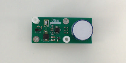
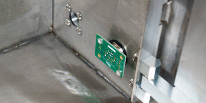
To fit the two sensors, simply align the legs on the sensor board with the holes on the connector board and push into place. Then, fix the sensor board to the connector board using the screws provided.
The main chamber of our glove box and the antechamber each have their own sensors. These are found on the right wall of the main glove box chamber and on the back wall of the antechamber.
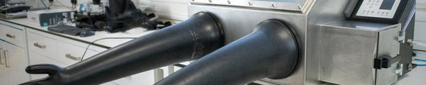
Glove Box Gloves
Our system comes with a pair of glove box gloves, and 4 O-rings. The gloves are made of butyl rubber which has low moisture and O2 ingression. Use two O-rings per glove to fix them securely in place.
To attach the gloves, pull them over the two ports and secure them in place with two of the O-rings provided. These should be tight enough to hold the glove in place, ensuring a tight seal.

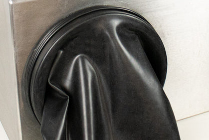
Make sure that you check the gloves regularly for wear and tear and replace them as soon as possible if you find any holes. While you can temporality seal small holes with black electrical tape, this is not a permanent solution, and you should replace the gloves as soon as possible.

Glove Box Window Assembly
Glove box screens consist of multiple layers and seals to ensure that minimal leaks occur around the window edge. There are many different types of seal, but the our system uses rubber gaskets to reduce leaks around the screen. These layers are secured into place using a metal frame.
To install the screen, first position the rubber gasket on the front panel by aligning the holes with the screws as below.
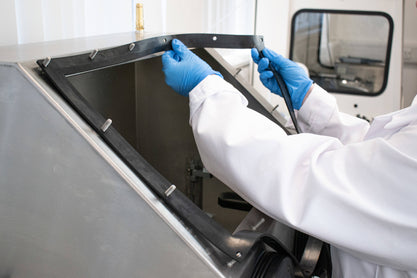
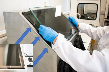

Once the rubber interlayer is in position, use the L spacers to align the glass window onto the front of the glove box. Next, place the final rubber gasket on top, slightly overlapping with the window edge. This provides cushioning between the screen and the metal frame.
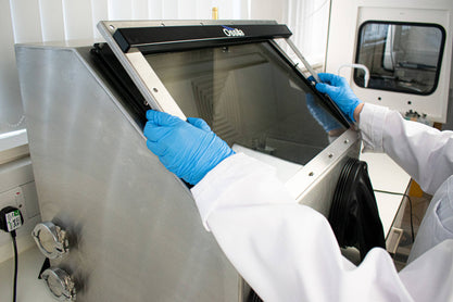
Once you have positioned all the gasket layers, place the metal frame on the front of the glove box and fix it into place using the domed nuts. First, tighten the domed nuts by hand, then secure with a wrench. Do not overtighten the nuts as this could cause damage to the glove box and compromise the seal.
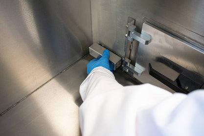
Glove Box Feedthrough Ports
The two ports on the left of the main chamber can allow electrical cable or vacuum feedthroughs into the glove box. There are various KF-flange feedthrough adapters which you can use for a power supply or vacuum lines. You can also assemble glove box feedthroughs for power, gas lines, or optical fibers using these ports. Alternatively, you can also seal these ports using the blank KF-flange provided.
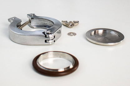
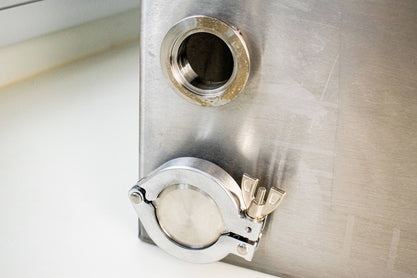
The blank KF-flange provided consists of a centering ring, a blank flange, and a hinge clamp.
To seal the KF-flange, line up the KF-flange blanking plate in combination with the centering ring. Then place these on the flange nipple.
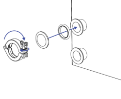
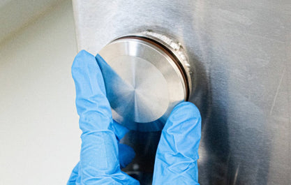
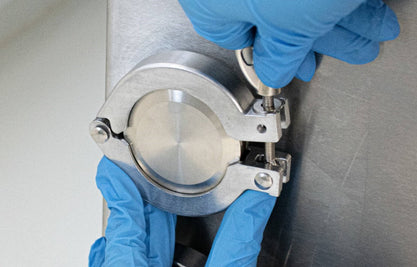
Finally, secure the seal into place using the hinge clamp and tighten until a tight seal is formed around the port.
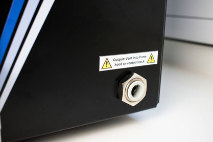
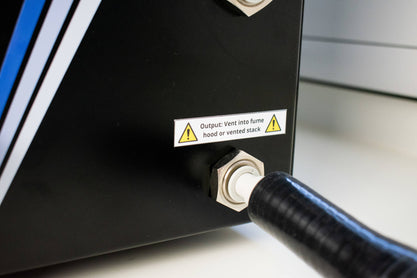
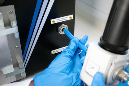
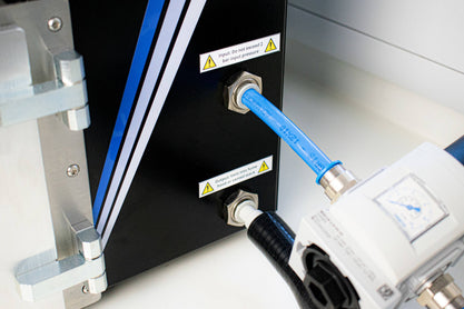
Inlet and Outlet Tubes
To insert the 12 mm inlet and outlet tubes, gently push the tubes into the correct feedthroughs into until they feel secure. We recommend using PTFE or metal pipes to decrease the ingression of moisture or oxygen into the glove box. This will also prevent the ingression of waste gas into the lab environment from the outlet tube.
If the outlet tube needs to be more than 1 m long to reach the ventilated area, we recommend converting to a tube diameter of 16 mm. For lengths longer than 3 m, you will need a wider diameter tube (>25 mm). You can use a conversion pipe to adapt the 12 mm outlet pipe, as shown below.
To insert the outlet tube, connect the 12 mm pipe to the outlet feedthrough. The other end of this line should vent into a fume hood or ventilated area.
Similarly, to install the inlet tube, push it into the upper bulkhead feedthrough. Next, connect this tube to a nitrogen supply which has been regulated to roughly 2 bar.
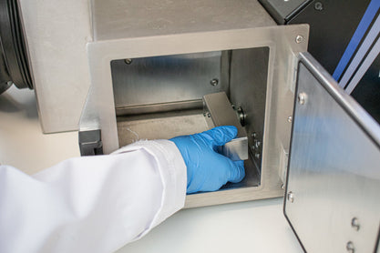
Pressure Relief Valve Assembly
Place the washer over the threaded end of the pressure relief valve and insert this end into the top corner of the glove box.
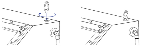
Tighten the valve using a wrench. The bottom nut can be used to tighten the relief valve.
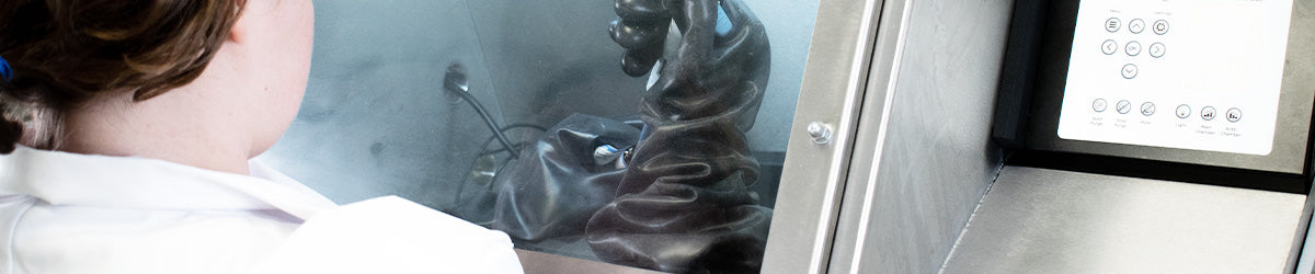
Starting the Glove Box
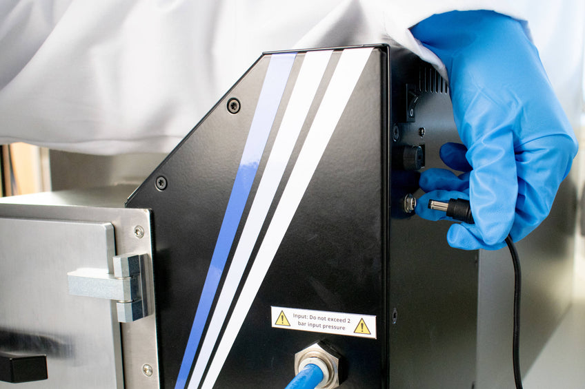
Once the glove box is completely sealed, simply plug into a wall socket, and turn on via the power switch on the back of the system.
The initial display is the Main Chamber Glove Box display page. This displays the oxygen and moisture levels and internal pressure within the main chamber.
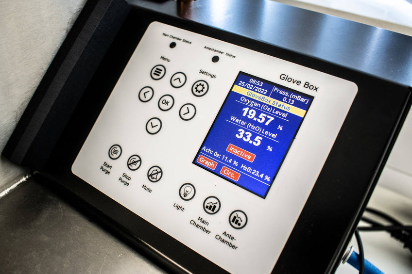
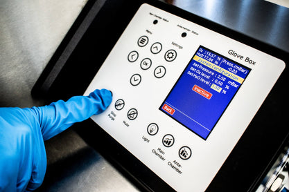
The first thing you need to do is set the time and date in the "Menu" section. This enables the glove box to accurately track the O2 and H2O levels, temperature, and pressure. This can be useful for identifying problems within the glove box.

Next, you need to set the overpressure, O2, and H2O levels. You can do this within the "Settings" section. We recommend that these are set at 1.5 mBar for the pressure, 0.5% for the O2 level and 1% for the H2O level. Once defined, press "Start Purge" to start the initial purge.

You will know the purge has begun when the button changes from "Inactive" (red) to "Active" (green). Additionally, the gloves will begin to inflate as the glove box aims to achieve the set overpressure.
Over the next few hours, the glove box will circulate nitrogen to reduce oxygen and moisture levels to below the desired levels. We recommend leaving the glove box for at least 12 hours to achieve a stable, inert environment.
You may find gas usage might be slightly higher for the first few days after first setting up the glove box if you have placed equipment with plastic casings in the main chamber, e.g. a spin coater or a hotplate. This is because this equipment will slowly degas into the main chamber over time. If you want to place equipment into the glove box, it may be a good idea to hold it under vacuum or dry it in a low temperature drying oven for a significant period of time before moving them inside the glove box. This will help degas the equipment before it is in an inert environment.
Once this is achieved the glove box is ready to use, and with regular maintenance, this environment can be sustained for an extended period.
Glove Box