Automated Solar Simulator Assembly

The Ossila Automated Solar Cell Testing Kit allows you to set up your solar cell testing lab quickly and easily. The kit includes:
- The solar cell I-V test system, which automatically switches between pixels when testing your devices.
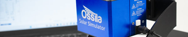
- Our solar simulator, which is calibrated to deliver 100 mW/cm2 irradiance uniformly over an area positioned 8.5 cm beneath the lamp.
- A positioning bracket to align your solar simulator and testing system, ensuring the calibrated light hits the surface of your substrate (system is compatible with either S211 or S2006 substrates).
The system is designed to be easy to use and effortless to assemble.
Assembly
To assemble the kit:
- Attach the positioning bracket to the solar cell I-V test unit.
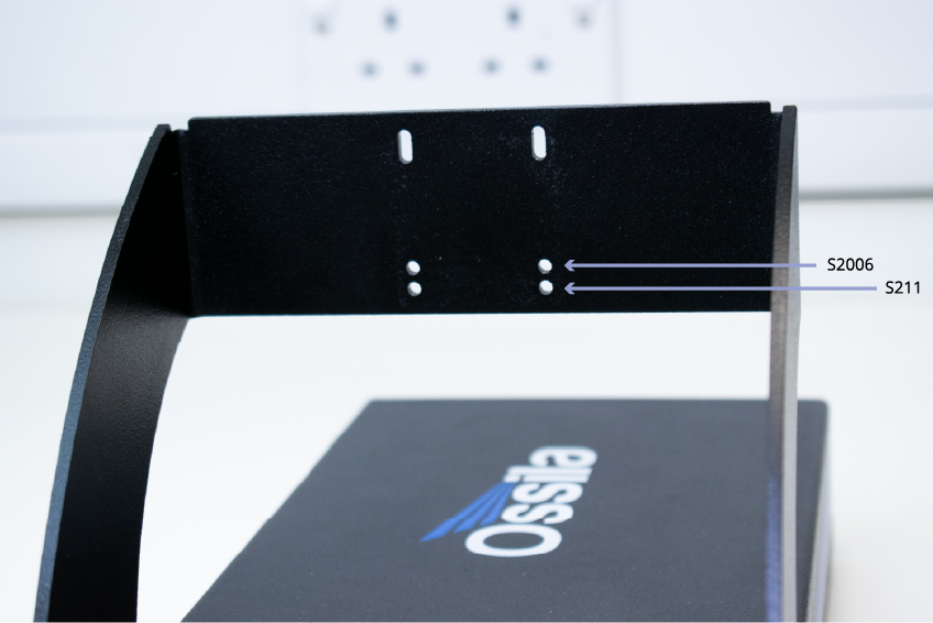
- To attach the solar simulator, loosely attach the two lower bolts. Position the solar simulator on these lower bolts. Make sure you use the right holes for your substrate type.
- Once the solar simulator is in position, fix in place with the upper two bolts, and tighten all M3 bolts to secure the head.
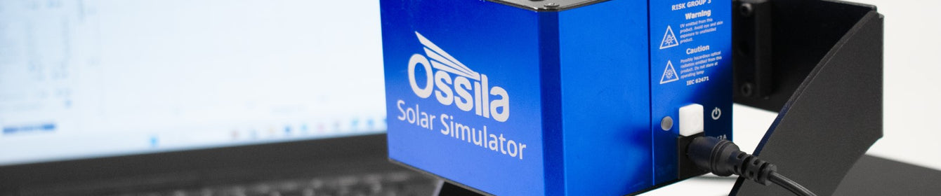
- Plug in the power cable and switch the lamp on.
Device Measurement
Our solar simulator is calibrated so that it delivers 100 mW/cm2 at a point 8.5 cm underneath the bulb. However, you can also use the Ossila Solar Simulator Console to manually control the irradiance and spectral output of the lamp.

Additionally, this system is compatible with the Ossila Solar Cell I-V Software. Using this software, you can easily characterized your solar cell devices without writing any code. The solar cell I-V software can take various measurements with the touch of a button. These include:
- J-V curves
- Lifetime data
- Stabilized current measurements
Substrate Type
The kit is compatible with our S211 substrates (area 20 x 15 mm) and our S2006 substrates (area 25 x 25 mm).
The testing boards for these different substrates have slightly different heights. Therefore, the solar simulator should be positioned slightly differently on the bracket, depending on the substrate board you are using.
If you are using the S211 test board, you should use the lower holes as shown. Alternatively, you should use the higher position holes, if the S2006 bracket is attached.
Automated Solar Cell Testing Kit