SMU Measurements: The Basics, I-V Curves, and Voltage Tracking
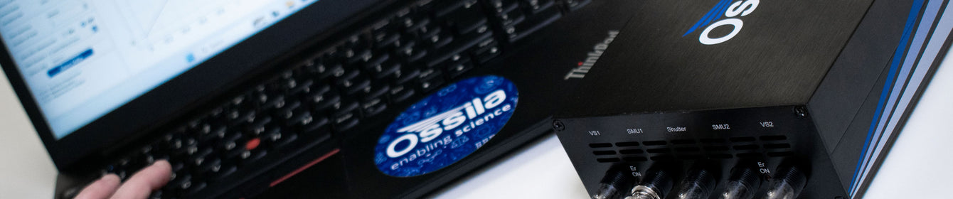
The Ossila Source Measure Unit (SMU) is a versatile instrument designed for the precise testing and measurement of small devices and films within a voltage range of -10V to 10V, capable of measuring currents up to 200 mA. Learn how to conduct various SMU measurements such as solar cell I-V curves, external voltage tracking, and basic quick measurements.
Basic Measurements with the Ossila SMU
You can take basic measurements and quick readings with our source measure unit. Through a single SMU channel, you can source voltage whilst measuring the resultant voltage and current. For each measurement, you must select or define certain measurement parameters.
- Turn on the SMU and connect it to your computer source via USB. Synchronize your device with the Front Panel software using the connect icon.
-
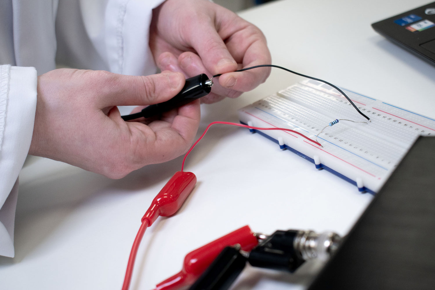
To set-up the measurement, insert the BNC cable into one of the SMU channels. Interface the other end of the cable with whatever device or measurement aids you are using. This end can be connected to a circuit using crocodile clips, or to one of our compatible testing boards.
-
Define the parameters of your measurement. When taking a basic measurement, you need to choose:
- Applied voltage. The voltage that the SMU channel is sourcing to the connected components.
- Current range. The range of current values over which the SMU will measure. It defines the upper limit and sensitivity of current measurements that can be performed by the SMU channel.
- Voltage limit. Sets the maximum voltage that the SMU channel can source (default ±10.5 V). If the measured voltage is above the voltage limit, the output voltage will be set to 0 V.
- Current limit. Sets the maximum current that the SMU can measure. If the measured current is above the set current limit, the range will automatically switch to ±200 mA to prevent damage to the SMU. If the SMU is already at ±200 mA, the output voltage will be set to 0 V.
-
Samples per point. Sets the number of measurements (or samples) taken for each data point. A higher number of samples per point will improve the accuracy of a measurement, but will increase the time taken for it to be performed.
- After choosing these values, press the start button in the software to start a ‘Data Plots’.
- For an instantaneous numerical measurement, you can press ‘Log Data’ at the top of the UI. This is stored in ‘Logged Data’. You can export this data automatically as an Excel file, see the voltage and current plotted live, or take an instantaneous reading of the data to be logged. All of the data can be saved and exported.

I-V Curve Measurements with the Ossila SMU
The Ossila Source Measure Unit can also perform an I-V sweep, constructing an I-V curve. This is made much easier using the corresponding I-V curve software. Again, you only need to use one SMU channel. This measurement type has its own set of parameters.
The setup for an I-V curve measurement is exactly the same as for a basic measurement:
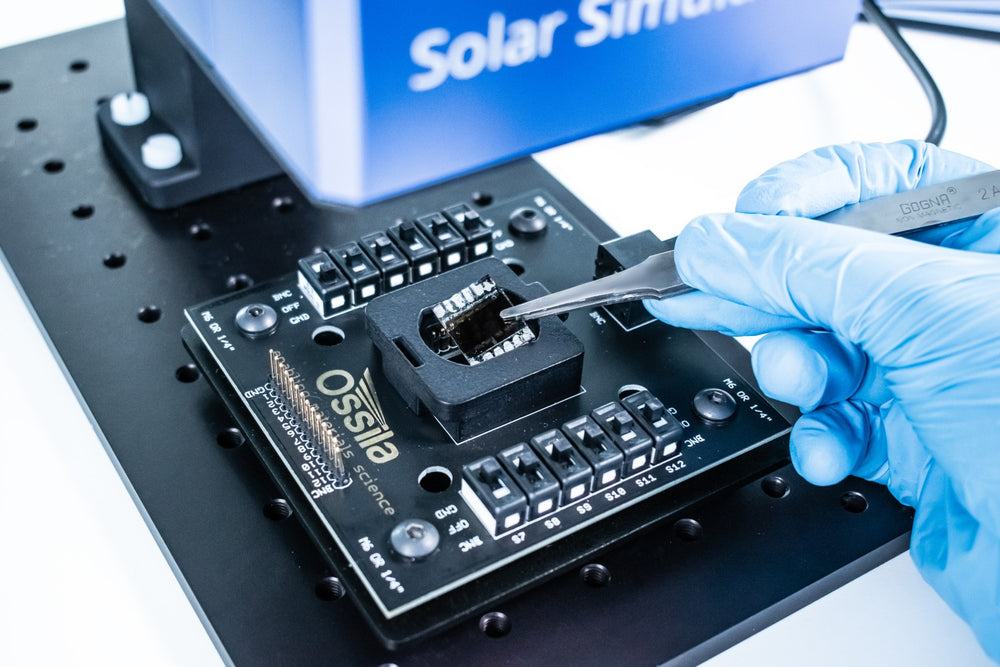
- Plug in the BNC connector to one of the SMU channels. The other end connects to your device or measurement interface. Our electrical test boards are ideal for device testing, as they allow you to switch between pixels easily.
- Define your parameters:
- Start and end voltage. The maximum and minimum voltage values that the SMU will sweep through and measure current.
- Current range. The range of current values over which the SMU will measure. It defines the upper limit and sensitivity of current measurements that can be performed by the SMU channel.
- Samples per point. Sets the number of measurements (or samples) taken at each data point. A higher samples per point number will improve the accuracy of each point, but increases the overall sweep time.
- Voltage step. Sets the step size in volts for changing the voltage during current-voltage measurements.
- Voltage settle time. Sets the time in seconds between outputting a new voltage and measuring the current.
- Hysteresis. If hysteresis is on, the software will perform a reverse current-voltage measurement after the forward current-voltage measurement has completed. This will measure any hysteresis affects, which is an important behavior exhibited by many devices (such as some solar cells).
- Secondary value. Voltage in volts to be output by the SMU channel not selected in the Voltage Source field. If the secondary voltage is set to 0 V, the secondary SMU channel will not be used. This secondary voltage channel is useful for OFET Testing.
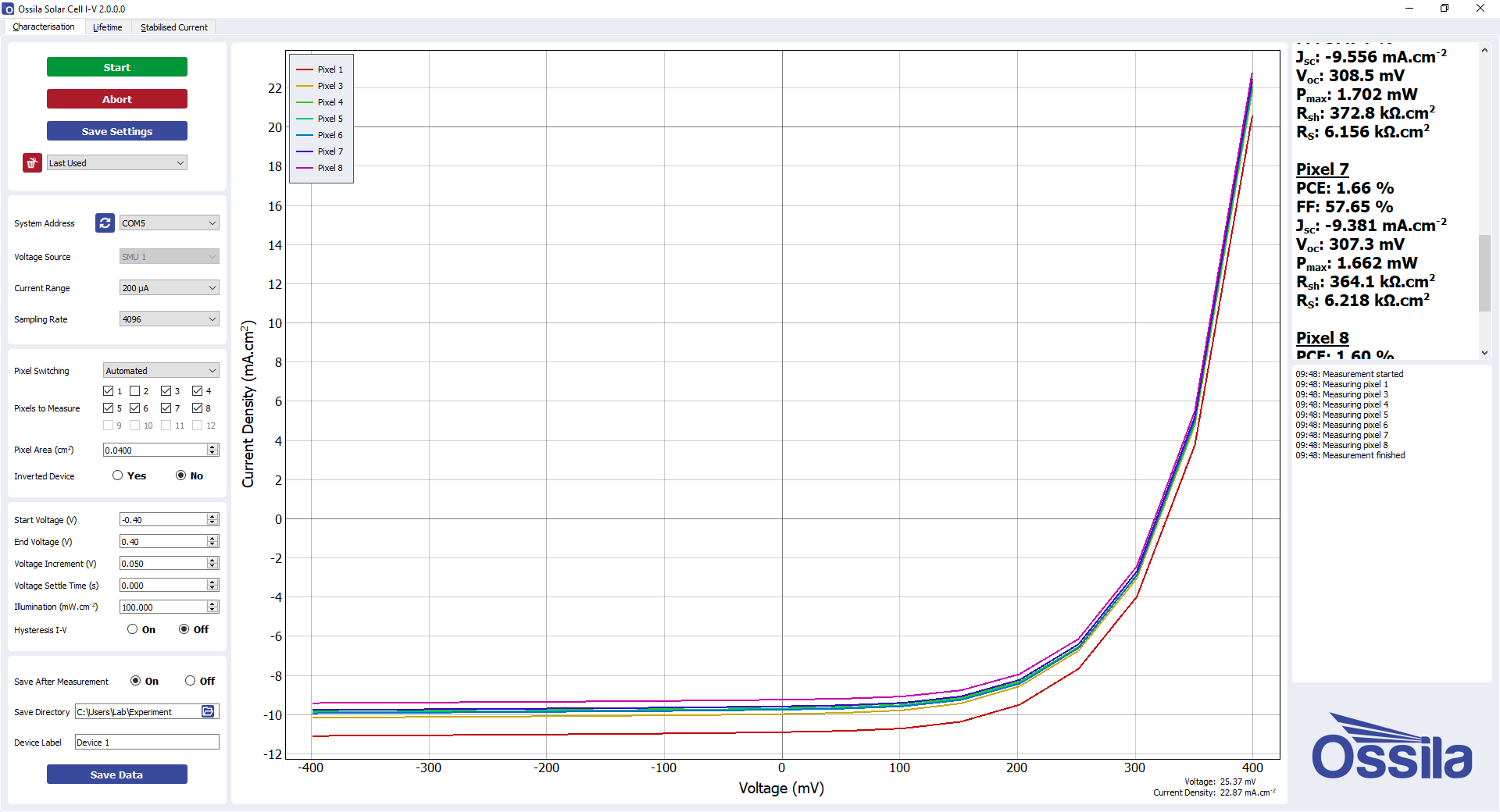
- After all parameters are specified, press the green ‘Measure’ button and the SMU will perform an I-V sweep.
- Again, the data from this measurement can all be saved and exported.
As well as our general I-V Curve Software, we also have specific software for testing solar cells (the Ossila Solar Cell I-V Software). This is also compatible with the our SMU which be combined with the Ossila Solar Simulator.
Voltage Measurements with VSense Channels
The source measure unit has two seperate Vsense channels that can be used to measure external voltages. To measure external voltages:
- Plug the BNC connector into one of the VSense channels, not one of the SMU channels. External voltage sources should not be connected to the SMU channel. Then connect your device to the other end of the cable.
- With a VSense measurement, there are no parameters to specify.
- Simply connecting the device and pressing the ‘ON’ button will display a live numerical reading and/or a live plot of the measured voltage. A instantaneous data log can be produced.
Even though there are no parameters to specify prior to measurement, the absolute maximum input voltage for the Vsense channels is ±12 V. It is also important that you do not apply input while not powered.
Source Measure Unit