Laminar Flow Hood Design
The design of a laminar flow hood (LFH) is critical to the quality of its performance. To optimize the performance, various design features must be considered and tested. Components such as the filter system, fan system, and structure greatly influence the air cleanliness, speed, and uniformity.
Designing a Laminar Flow Hood
Filtration
A high-quality air filtration system is necessary to achieve a clean air environment. Laminar flow hoods are equipped with a high-efficiency particulate air (HEPA) filter. HEPA filters trap particles and contaminants of varying sizes. Our hood also includes a coarse pre-filter to remove large particles from the air before it passes through the HEPA filter. This extends the lifespan of the HEPA filter and reduces maintenance costs.
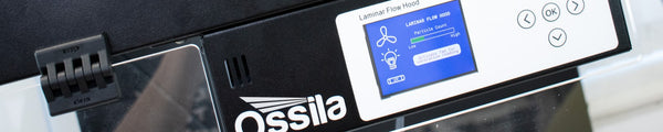
Typically, LFHs do not report on the cleanliness of the air in the workspace. This leads researchers to discover air contamination only when the experiment has failed. To prevent this issue, the Ossila Laminar Flow Hood uses the particle sensing technology found in clean rooms. Our hood continuously monitors the cleanliness of the workspace air and provides you with feedback as you work. This design feature improves the reliability of sensitive experiments conducted using laminar flow hoods and prevents wasted time when contamination is not identified.
Speed
The fan and filter are the most important design consideration. They work as one unit to achieve the right air flow speeds for laminar flow. Two critical specifications to consider when choosing these components are:
- The pressure drop of the filter
- The total volumetric air flow for the equipment
The pressure drop refers to the difference in pressure needed between the back and front face of a filter to ensure a specific air flow rate. This value is dependent upon the porosity of the filter and the target air flow rate. Lower porosity and higher air flows require higher pressure differences. For HEPA filters in a laminar flow hood a typical initial pressure drop is around 90 to 120 Pa.
The total volumetric air flow is determined by the area of the filter and the required air speed. For laminar flow, the air speed typically ranges from as low as 0.3 m.s-1 to 0.7 m.s-1. Air speeds above this can easily break down into turbulent flow, while air speeds below this will be too slow to maintain laminar flow for the entire length of the cabinet.
By taking these values into account, we can select a motor that can provide the necessary air flow at the required back pressure for the filter to function properly.

By taking these values into account, it is possible to pick the motor best suited to your needs. The chosen motor must have the capacity to deliver the precise air flow rate needed to meet the required back pressure for the filter.
Uniformity
The uniformity of air flow depends on the design of the LFH itself and the plenum, where the HEPA filter is located. The plenum design affects how the air emerges from the filter, while the hood design determines the spread and movement of the air after leaving the filter.
Optimizing the plenum design has the greatest impact on the uniformity of air flow. Air movement is modeled with different geometries to ensure pressure uniformity and optimal flow trajectories at the face of the HEPA filter. Our laminar flow hood is built following thousands of hours of simulation time. Both fan behavior and the impact of different geometric designs on the air uniformity have been modeled. This has allowed us to create an optimal plenum shape and size, as well as motor mounting, to ensure high uniformity in both the vertical and horizontal orientations.
To maintain air flow uniformity, it is important to minimize zones where stagnant air can form. These areas can trap contaminants, which may later be disturbed and spread within the hood, potentially affecting samples. Flat surfaces with a minimal number of protrusions are crucial to avoid interrupting the laminar flow. Our LFH minimizes seams and places mating fixtures outside the working area to reduce the chances of stagnant air pockets.
Bringing the Design Together
The design of a laminar flow hood ensures that the air flow remains laminar throughout the workspace. By matching the back pressure and flow rate characteristics of the motor and fan with those of the filters, the air velocity is finely tuned. Additionally, fluid simulation is used to optimize the design of the plenum, controlling the air flow from the motor to the filter. This guarantees consistent air velocity across the face of the hood, offering reliable performance.
Optimal design and the inclusion of particle sensing technology, ensures our LFHs create and maintain a clean air environment that meets ISO class 5 standards. The structure of the Ossila laminar flow hoods offer a changeable configuration, providing adaptability to different experimental set-ups.
Laminar Flow Hood
Contributing Authors
Written by
Product Developer