Cyclic Voltammetry Basic Principles and Theory

CV Theory and Principles | Cyclic Voltammetry Graph Explained | Cyclic Voltammetry Set Up | Applications of Cyclic Voltammetry

Cyclic voltammetry (CV) is an electrochemical technique used to study the oxidation and reduction of an analyte. In a typical CV measurement, the potential sweeps linearly across a set voltage range (first forward, then in reverse) while recording the corresponding current using a potentiostat.
The resulting plot has a famous duck-like shape that provides essential information about the thermodynamics of redox processes, and electro-kinetics related to electron-transfer reactions. Some of the most useful values are the anodic and cathodic peak currents and potentials, the polarographic half-wave potential, and the oxidation and reduction onset potentials. In materials science, this data can be used to probe qualitative and quantitative information about the electrochemical properties of chemicals.
Cyclic voltammetry is often used to:
- Investigate the reversibility of a reaction
- Describe electron transfer kinetics
- Approximate the energy levels of semiconducting polymers
Cyclic voltammetry can also be used to characterize conductive polymers, battery materials, supercapacitors, and a range of electrocatalysts. This is also useful for investigating new energy materials for growing technologies including green hydrogen production, electrochemical carbon capturing, fuel cells, electrochemical sensors and other electron transfer processes.


Cyclic Voltammetry Theory
Cyclic voltammetry is a voltammetric technique that applies a triangular potential waveform to an electrochemical cell. This potential is swept linearly through a defined potential window, with a set starting potential (often the open circuit potential), switching potential, and end potential. This cycle can be repeated multiple times. The electrochemical response can also be affected by the scan rate or sweep rate (the rate of change of potential), and this should be carefully considered.
Potentiometry vs. Voltammetry
Potentiometry is a way of measuring the electrical potential of an electrochemical cell under static conditions (i.e. no current flow).
For a general reduction or oxidation (redox) reaction, the standard potential is related to the concentration of the reactants (A) and the products (B). This occurs at the electrode/solution interface and can be recognized according to the Nernst equation:


Here, E is the electrode potential, E0′ is the formal potential, R is the gas constant (8.3145 J·K-1·mol-1), T is temperature, n is the number of moles of electrons involved and F is the Faraday constant (96,485 C·mol-1).
The term [B]b/[A]a is the ratio of products to reactants, raised to their respective stoichiometric powers. You can use this in place of an activity term when the concentration is sufficiently low (< 0.1 mol·dm˗3).
Under standard conditions of temperature and pressure, the Nernst equation can be written as:

Voltammetry is any technique that involves measuring the current while varying the potential between two electrodes. Voltammetric methods include cyclic voltammetry and linear sweep voltammetry, as well as similar electrochemical techniques such as staircase voltammetry, squarewave voltammetry, and fast-scan cyclic voltammetry.
In voltammetry, the current is generated by electron transfer between the redox species and the two electrodes. The diffusion and migration of ions carries this current through the solution.
Three Electrode Electrochemical Cells
In principle, cyclic voltammetry (and other types of voltammetry) only requires two electrodes. However, in practice it is difficult to keep a constant potential while measuring the resistance between the working electrode and the solution. This is made more difficult as you try to pass the necessary current while also passing current to counteract the redox events at the working electrode.
It is the three-electrode system that separates the role of referencing the potential applied from the role of balancing the current produced. Most electrochemical cell kits, like the Ossila Standard Electrochemical Cell Kit, consists of a standard electrochemical cell along with a working electrode (WE), Reference electrode (RE), Counter Electrode (CE). However, the exact electrochemical cells and electrodes required for specific experiments will depend on the electrolyte and the specifics of the application.
To measure and control the potential difference applied, the potentiostat varies the potential of the working electrode while the potential of reference electrode remains fixed by an electrochemical redox reaction with a well-defined value.
To keep the potential fixed, the reference electrode must contain constant concentrations of each component of the reaction, such as a silver wire, and a saturated solution of silver ions.
To remove the risk of contamination, it is sometimes recommended to set up the electrochemical cell inside a glove box.
It is important to note that minimal current passes between the reference and the working electrodes. The current observed at the working electrode is completely balanced by the current passing at the counter electrode, which has a much larger surface area.
The current in the solution is carried by ions (migration). Near the electrode surface, a electric double layer (EDL) forms, acting like a tiny capacitor. The actual current we measure comes from the analyte moving to the electrode (diffusion) and swapping electrons. We calculate this relationship using Faraday’s and Fick’s laws in the following combination:

Where id is the diffusion-limited current, A is the electrode area, D0 is the diffusion coefficient of the analyte and (∂C0/∂x0) is concentration gradient at the electrode surface.
The product of the diffusion coefficient and concentration gradient can be thought of as the molar flux (mol·cm-2·s-1) of analyte to the electrode surface.
Cyclic Voltammograms Explained
A cyclic voltammogram is the ‘duck-shaped’ plot generated by cyclic voltammetry. In this example cyclic voltammogram, the scan starts at -0.4 V and sweeps forward to 0.3 V then back to -0.4 V. There are several key stages which make up this “duck-shaped” curve.

-
Measuring the Baseline: Double Layer Charging
In the forward sweep, the potentiostat linearly increases the working electrode (WE) potential compared to the reference electrode. This is also known as an anodic scan or oxidative scan. As this potential increases, negatively charged ions (anions) are attracted towards the electrode forming a layer next to the WE called ‘Inner Helmholtz’ layer. Subsequently, these anions attract positive ions in the solution which forms an outer Helmholtz layer, and a further diffuse layer. All together these layers form the “Electrical Double Layer”. In an aqueous medium, even though negative ions anions present as solvated individual anions (ex. Cl-), positive ions (cations) exist almost exclusively as complexes, bonding with water molecules to form aquo complexes (ex. [Na (H2O)6]+). Hence the transport speeds (diffusion) of cations are rather limited inside an aqueous solution. The electric double layer is a complex environment, which acts as a physical capacitor. Hence in absence of a redox analyte, CV curve will look rectangular.
The current-voltage behavior of this region is mostly flat after an initial hike, which depends on the surface area of the electrode. This process is therefore ‘surface-controlled’ and this region is called the capacitive region. Minimal chemical reactions are expected to occur in this region and current is dependent on the double layer capacitance (Cdl)

Where ν is the scan rate.
In the example cyclic voltammogram above, the scan starts at -0.4V and sweeps forward to more positive, oxidative potentials. Initially the potential is not sufficient to oxidize the analyte.

-
Initial Current Rise: Kinetically Driven
As the voltage increases towards the formal potential (E0), the system reaches the onset potential (Eonset) of oxidation. After this potential, the analyte will start affecting charge transfer. This potential is high enough to draw the electrons away from the analyte, directly transferring into the working electrode. This leaves behind the oxidized analyte at the electrode surface.

In this stage, the current rises exponentially. The current in this region is dominated by the electron transfer speed so is kinetically controlled. At this stage, the reactions are determined by the Butler-Volmer equation.

Where η is overpotential (the extra voltage applied beyond the equilibrium potential), α are the charge transfer co-efficients, F is Faraday constant and i0 is the exchange current density.

-
Reaching the Anodic Peak: Diffusion Limited
As overpotential increases, the current also increases. However, as the scan continues, the more the analyte is depleted. The concentration gradient adjusts to this. At some point the reaction is occurring faster than the analytes travel to the electrode from the bulk solution. This triggers a significant drop of the analyte concentration at the electrode surface. The combination of these two factors results in an anodic peak current (ipa) for oxidation at the anodic peak potential (Epa). This is where the current reaches its maximum for oxidation. Here, any increase in current is offset by a decreasing flux of analyte, as the analyte comes from further and further distances from the electrode surface.
At the peak, the Nernst Equation and the Fick’s Law of Diffusion coincide. Past this point, the current is not kinetically controlled by charge-transfer, but by the mass transport (by diffusion) of unoxidized analytes to the electrode surface. The reaction is diffusion controlled, as explained by the Randles- Ševčík Equation, where the peak current (ip) directly corresponds to the square root of the scan speed.
The peak current, ip, of the reversible redox process is described by the Randles-Sevcik equation.
At 298 K, the Randles-Sevcik equation is:

Where n is the number of electrons, A the electrode area (cm2), C the concentration (mol·cm-3), D the diffusion coefficient (cm2·s-1), and ν the potential scan rate (V·s-1).
-
Initial Decline: Concentration Depletion
After the peak, the current reduces as the anodic scan continues increasing potential, due to the depletion layer is expanding.
This is a continuation of the time-dependent diffusion-controlled region, as the analyte must travel further as the anodic scan continues, and the current I(t) decays as a function of 1/ (t)1/2, following the Cottrell equation.


-
Reverse Sweep (Cathodic scan)
After the forward scan, the scan direction is reversed while current is continually measured. This is known as the cathodic scan or reductive scan. At first, the forward reaction (oxidation) still dominates, as the positive potential supports the oxidation reaction. When the potential reaches a specific point, the thermodynamics start to favour the reverse reaction (reduction). The working electrode starts donating the electrons to the oxidized analyte, replenishing the population of the original analyte.

-
Cathodic Peak
The process for reduction mirrors the oxidation process, as similar concentration, kinetic and diffusion processes affect this curve. The difference is that the reverse scan has an opposite scan direction and a cathodic peak (ipc) at the cathodic peak potential (Epc). If the process is completely reversible, the anodic and cathodic peak currents should be of equal magnitude but with opposite sign (assuming 100% of the oxidized analyte is reduced). The cathodic peak is measured relative to the base line after the anodic peak.
Cyclic Voltammetry of Ferrocene
Ferrocene (Fc) is a common internal standard for cyclic voltammetry. Its cyclic voltammogram can therefore be considered "typical". Like the general case which was described above, at the start of a cyclic voltammetry scan a positively ramping potential (the forward sweep) is applied between the working and reference electrodes. As the potential increases, ferrocene (Fc) physically close to the working electrode is oxidized (i.e. loses an electron). This converts it to Fc+, and the movement of the electrons creates a measurable electrical current.
As un-reacted Fc diffuses to the electrode and continues the oxidation process, the electrical current is increased and there is a build up of Fc+ at the electrode. This build up of Fc+ and depletion of Fc is called the the diffusion layer, and effects the rate at which un-reacted material can reach to the electrode. Once the diffusion layers reaches a certain size, the diffusion of Fc to the electrode slows down, resulting in a decrease in the oxidation rate and thus a decrease in electrical current.
When the potential ramp switches direction, the process reverses and the reverse sweep begins. Fc+ close to the working electrode reduces (i.e., gains an electron), converting it back to Fc. The electrical current flows in the opposite direction, creating a negative current. The Fc+ diffuses to the electrode, reducing to Fc and resulting in a increase in the negative current.
How to Read a Cyclic Voltammogram
Reading a cyclic voltammogram is relatively straight-forward. The diagram below shows a cyclic voltammogram for ferrocene as measured by an Ossila Potentiostat. Labels have been added to show key data points.

Charging currents and uncompensated resistance
In addition to the resistance from the redox reaction taking place on the surface of the working electrode, electrochemical cells also exhibit solution resistance between the working electrode and reference electrode. The size of this resistance can be minimized by placing the working electrode close to the reference electrode. It is impossible to completely eliminate solution resistance in a cell so when reading a cyclic voltammogram, it is important to consider the effects of uncompensated resistance. Large uncompensated resistance can falsely make a reaction look quasi-reversible or irreversible.
A second effect that can affect the reading of a cyclic voltammogram is from charging currents. Charging currents can be minimized by decreasing the scan rate or using a working electrode with a smaller surface area, but it is generally preferable to subtract them from the data. This can be done to first approximation by either subtracting the current observed when no redox reactions occur or by taking a cyclic voltammogram without the sample of interest present and subtracting the results of this scan from the cyclic voltammogram of the redox event. Neither of these approaches is valid at extremely fast scan rates but they are useful approximations for cyclic voltammetry experiments at "normal" scan rates. After charging currents have been subtracted, the baseline (pre-redox event) should be equal to the zero-current line. Ipa and (Ipa)0 should therefore be equal. Although the charging currents in the cyclic voltammogram shown above are small, the labels would only be numerically accurate after they have been subtracted from the data.
Anodic peak current and anodic peak potential
The anodic peak current (Ipa) occurs at the anodic peak potential (Epa) and is measured relative to an extension of the baseline in the zero-current region. In the IUPAC convention for cyclic voltammograms, the anodic peak current is positive.
Cathodic peak current and cathodic peak potential
The cathodic peak current (Ipc) occurs at the cathodic peak potential (Epc) and is measured relative to an extension of the reverse sweep baseline. This is more difficult to obtain than the forward sweep baseline; its shape resembles a reflection of the voltammogram had the direction of the scan not been reversed. The reverse sweep baseline can be approximated mathematically, or alternatively, the ratio between the cathodic and anodic peaks can be approximated using the Nicolson parameter. To do this, the absolute cathodic peak current ((Ipc)0) and absolute current at the switching potential ((Isp)0) need to be measured. The absolute cathodic peak current is taken relative to zero-current rather than the baseline, and hence is easier to determine than Ipc. For a reversible reaction, the cathodic peak will be of equal magnitude to the anodic peak, but with the opposite sign.
Polarographic half-wave potential
The polarographic half wave potential (E1/2) is often used to approximate the formal and standard potentials. For reversible or quasireversible reactions, it can be approximated as the average of the peak cathodic and anodic currents.
Oxidation and reduction onset potentials
The oxidation onset potential (Eonset) is the potential at which the analyte oxidizes at the surface of the working electrode, causing the current to increase exponentially on the cyclic voltammogram until it reaches the anodic peak current. A similar point (not shown) on the cathodic peak exists for the reduction onset potential. Onset potentials correlate with the HUMO and LUMO energies of a material and are sometimes used instead of the half-wave potential when determining the potential of a redox event.
IUPAC convention vs. US convention for cyclic voltammograms
There are two main conventions for cyclic voltammograms; the International Union of Pure and Applied Chemistry (IUPAC) convention and the US (or “classical”) convention. The cyclic voltammogram above uses the former. In the IUPAC convention, the oxidative potential sweep runs from left (negative values) to right (positive values) along the x-axis. Conversely, the reductive sweep runs from right to left. On the y-axis, the anodic peak is positive and the cathodic peak is negative.
In the US convention, the cyclic voltammogram is - in effect - rotated by 180 degrees compared to the IUPAC convention. The x-axis runs from positive values to negative values, showing increasing reduction left to right and oxidation from right to left. In this convention, the anodic peak is negative and the cathodic peak is positive. This changes the form of some of the equations (e.g. the Nicholson Parameter) on this page. Both conventions are common in the literature so care should always be taken when working with cyclic voltammetry.
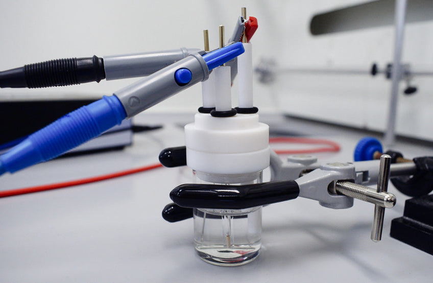
Cylic Voltammetry Set Up
Like other types of voltammetry, cyclic voltammetry uses a three electrode system consisting of a working electrode, reference electrode, and counter electrode. During a scan, a potentiostat linearly sweeps the potential between the working electrode and reference electrode while measuring the current between the working electrode and counter electrode. The potential is swept in both directions (within the defined potential range) for the set number of cycles.
To set up and run a cyclic voltammetry scan with the Ossila Potentiostat:
- Switch on the potentiostat ~30 minutes before use to allow it to warm up and reach a stable temperature
- Add the reference solution to the reference electrode tube with a syringe and needle until it is approximately two-thirds full
- Clean the working and counter electrodes using the same solvent as used for the electrolyte
- Place a droplet of solution containing the sample onto the tip of the working electrode and allow it to dry
- Insert each electrode into the electrochemical cell cap
- Gently bubble inert gas through the solution for ~10 minutes using a thin tube or needle to remove dissolved oxygen
- Connect the electrochemical cell to the potentiostat using crocodile clips
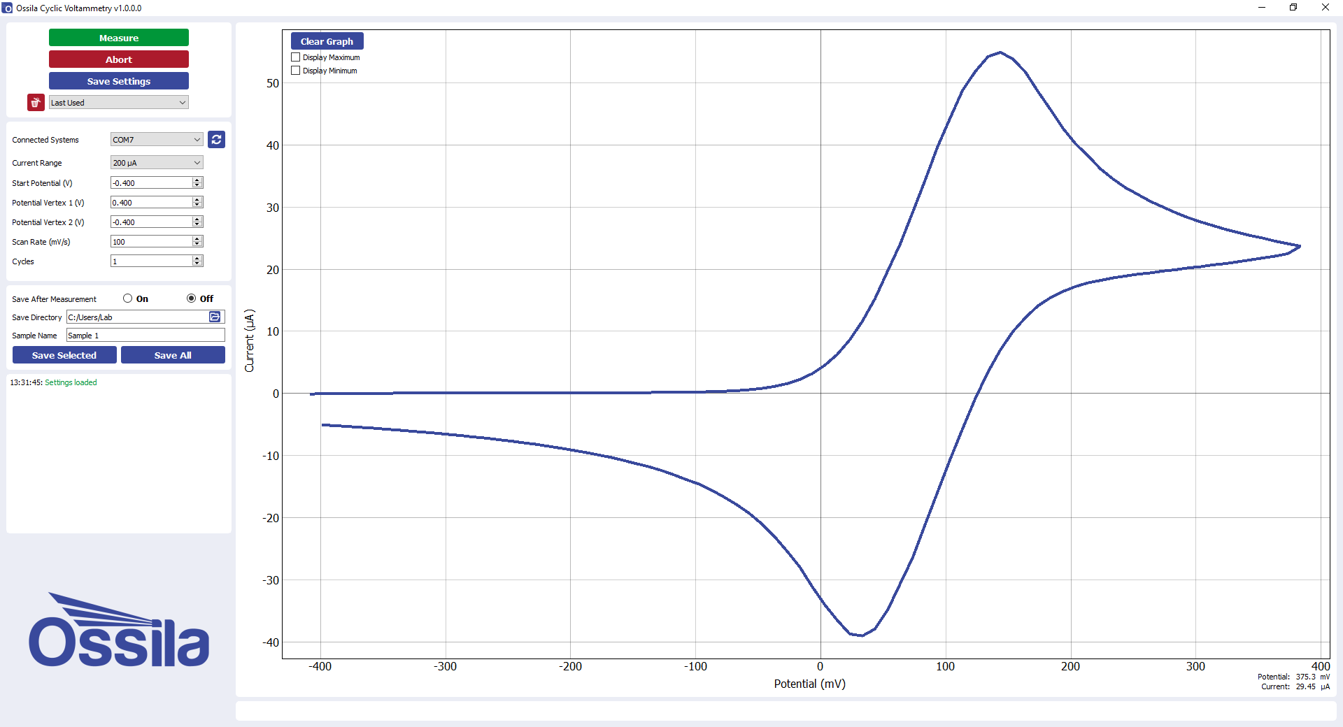
- Start the software and set the current and potential ranges to appropriate values for the sample in question
- Withdraw the degassing tube/needle and start the measurement via the software
Successful cyclic voltammetry measurements produce a 'duck-shaped' plot known as a cyclic voltammogram. Analysis of the cyclic voltammogram reveals information about the sample.
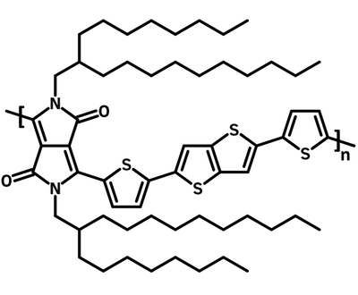
Cyclic voltammetry of PBDB-T-2Cl over a 2 mA range using a 0.01 M solution of silver nitrate in acetonitrile as the reference solution
Potentiostat

Applications of Cyclic Voltammetry
Determining the Reversibility of a Reaction
What determines the reversibility of a reaction?
The reversibility of a reaction can be split into two metrics, chemical reversibility and thermodynamic reversibility.
- If an electron transfer can be reversed without any side reactions (either before or after) then it is said to be chemically reversible
- If the rate of electron transfer is sufficient that equilibrium is maintained, then it is said to be thermodynamically reversible
- If both thermodynamic and chemical reversibility are observed, the electron transfer is said to be reversible i.e. there is practical reversibility
Practical reversibility does not necessarily mean that no side reactions ever occur, or that the system cannot be perturbed from equilibrium; it only requires equilibrium and a lack of side reactions on the time scale of the experiment. For example, a reaction would still be considered reversible if the oxidized compound slowly degrades over time, providing that a sufficient scan rate (rate of potential change) is used. Similarly, even if thermodynamic equilibrium is not maintained at very fast scan rates, the reaction is still considered reversible if it is maintained during the cyclic voltammetry experiment.
Linear diffusion
All the equations on this page assume linear diffusion. Most electrodes can be approximated as having linear diffusion on short time scales. The larger the electrode, and the shorter the time observed, the more the linear diffusion approximation applies.
How to determine the reversibility of a reaction
Cyclic voltammetry can be used to measure two parameters, which can together can be used to determine if a reaction is reversibly for a given scan rate. These are:
- The difference in the potential difference between the anodic peak current and the cathodic peak current
- The height of the anodic and cathodic peaks relative to the baseline (note: for the reverse peak, the baseline after the electron transfer is used)
The Nicholson parameter
For an oxidation, the height of the peak cathodic current (ipc) can be hard to determine, and likewise, the peak anodic current can be difficult to determine for a reduction. As a result, a variety of methods are used for determining the ratio of the cathodic and anodic peaks. To do so from a single experiment without fitting the curve, the Nicholson parameter is often used.

In this equation, isp is the absolute current at the switching potential, ipc is the absolute current at the cathodic peak potential, and ipa is the absolute anodic peak potential. The (…)0 notation simply indicates that the currents are taken relative to the i=0 line.
The Nicholson parameter only gives accurate results when the switching potential is 60/n mV past the peak anodic potential for an oxidation, and -60/n mV for a reduction.

Charging currents
When measuring the currents required to calculate the Nicholson parameter, the charging currents need to be neglected. In cyclic voltammetry, these are approximately constant for each linear sweep, but their direction changes depending on the direction of the sweep. It is this effect which leads to hysteresis in the cyclic voltammogram when no reduction or oxidation occurs (i.e. in the absence of redox active species).
To first approximation, the charging currents can be neglected simply by running a voltammogram without redox active species present and subtracting the results from the actual voltammogram. Alternatively, they can be subtracted by looking at the steady current when no redox reactions occur, and subtracting this for forward and reverse runs.
Though they do improve the quality of the results obtained, neither of these approaches are perfect. Specifically, both methods are prone to errors at faster scan rates, such as those which are accessible at ultramicroelectrodes .
Uncompensated resistance is the resistance to charge flowing outside the electrochemical process at the electrode. Large uncompensated resistance resulting from the movement of charges in solution can make the system look quasireversible or irreversible, even when it is not.
More accurate results can be obtained from fitting the system with more complex equations or by using specially designed instruments.
Reversible reactions
For a reversible reaction, ipa/ipc=1, and Epa-Epc=0.52/n V for an oxidation, and -0.52/n V for a reduction, where n is the number of electrons in the oxidation or reduction.
Quasireversible systems
A quasireversible system is where the scan-rate and the electron transfer rate compete, such that thermodynamic equilibrium is never reached. A cyclic voltammogram which still has both anodic and cathodic peaks, but does not have Epa-Epc=0.52/n is considered quasi-reversible.
Irreversible reactions
If the reverse peak is missing, an electron transfer is classified as irreversible. Note that if ipa/ipc≠1, then the reaction is not chemically reversible. This suggests that another reaction is taking place in addition to the oxidation and reduction of the compound (i.e. O+n e-⇌R). When additional chemical reactions occur, there is said to be coupled reactions.
Using Half Wave Potentials to Estimate Formal Reduction Potential
The formal potential is a measure of the potential of a cell where both oxidized and reduced species are present at equal concentration. The formal potential is defined via potentiometry, which involves measuring the potential difference in a galvanic cell, but can be approximated with cyclic voltammetry.
The Gibbs free energy
This potential difference is related to the Gibbs free energy, which corresponds to the overall reaction when there is oxidation at the left electrode and reduction at the right electrode.
The Gibbs free energy can be calculated using the following formula:

The standard potential and standard reduction potential
The "standard potential" is the potential where all species are present with unit activity. To allow standard potentials to be compared across different systems, a universal convention was adopted in which all reactions are expressed as reductions, and measured relative to the standard hydrogen electrode (SHE). These values are known as standard reduction potentials.
It is possible to calculate the standard potential of a cell (Ecell0), from the standard reduction potential of the redox couples on the left (Eleft0) and the right (Eright0). The standard potential, i.e. the potential where all compounds are present under standard conditions, is given by the following:

The EMF of a cell with non-unit activity (E) can be related to the standard potential (E0) using the following formula, where ax is the activity of compound x, n the number of electrons involved in the oxidation/reduction, and T is the temperature:


The formal potential
Because the standard potential requires knowing the activity constant of both the oxidized and reduced compound, it is quite difficult to calculate. As such, the formal potential (E0') is frequently used instead. This is given by the following formula, where symbols are defined as previously defined, [X] is the concentration of compound x, and X is its activity constant.


How to approximate the formal potential with cyclic voltammetry
To approximate the formal potential with cyclic voltammetry, the polarographic half wave potential E1/2 is often calculated. For a reversible (or quasireversible) reaction, the formal potential is approximately the average of the peak cathodic and anodic potentials (known as the half wave potential).
The halfwave potential can be calculated more accurately by polarographic type methods, but in cyclic voltammetry, an accuracy of the order of mV can be observed for a reversible reaction.
The half wave potential (E1/2) is related to the formal potential (E0'), which in turn is related to the standard potential (E0). The relationship is shown below, where am is the activity of species m, [m] is the concentration, γm is the activity coefficient, and Dm is the diffusion constant.


In practice, the difference between E1/2 and E0' is minimal. As such, it is quite common to approximate E1/2=E0'.
Measuring Electron Transfer Kinetics
The kinetics of the electron transfer are often characterized in terms of the standard rate constant k0. k0 is the rate constant of both oxidation and reduction when the electrode is at the formal potential i.e. when E=E0'.
How to calculate the standard rate constant with the method of Nicolson
The standard rate constant can be calculated using the "method of Nicholson", if the diffusion constant of the species in solution is known. In his 1965 paper,[7] Nicholson calculated the separation of peak cathodic and anodic current for a reduction for various values of ψ:

Here, Do is the diffusion constant of the oxidized species, DR of the reduced species, v is the scan rate, n is the number of electrons involved in the oxidation/reduction, α is the transfer coefficient (see Butler-Volmer equation), T is the temperature, F is the faradays constant, and R is the gas constant.
It is possible to look up a value of ψ for a known separation of anodic peaks, and if all other constants are known, this value can then be used to calculate a value of k0. In addition, the diffusion constants of oxidation and reduction are usually found to be similar, so it is sometimes considered valid to approximate:

It should be noted these results are only reliable for 0.3<α<0.7, but this is commonly true.
For a reduction, as opposed to an oxidation, the same basic process applies.
A problem with this method is that the uncompensated resistance (resistance to charge flowing outside the electrochemical process at the electrode) can dominate the cyclic voltammogram. The uncompensated resistance is particularly an issue when reversibility is approached, and as such resistance in solution should be minimized.
Determining the Energy Levels of Semiconducting Polymers
A commonly used method for determining the energy levels of organic semiconducting polymers with cyclic voltammetry is to deposit the polymer on the working electrode and measure the electrical response
Depositing a solid on an electrode forms what is referred to as a modified electrode. The onset potential is usually then calculated, and this value is assigned as the energy of the HOMO and LUMOs.
The evidence for this method comes from a paper which tested the ability of Valence Effective Hamiltonian (VEH) to calculate redox potentials . In the paper, the onset potential and gas phase ionizations energies were observed to correlate with VEH calculated HOMO and LUMO. However, the absolute values show absolute error of the order of 0.1 V, in opposite directions for the two experimental techniques. Based on this evidence, the onset potentials are often used to calculate the HOMO and LUMO energies more generally. Here, HOMO is being used to mean the highest energy electron in the solid state, and LUMO the lowest energy excited electron (different from a theoretical description of HOMO and LUMO).
A modern electrochemical review, discourages the use of this method, claiming that onset potential "are not standard potentials, and do not posses thermodynamic significance".
Determining the Absolute Energy of Semiconductors
By using cyclic voltammetry to measure the potential at which redox events occur relative to a reference, it is possible to determine the energy levels at which a redox couple interconvert relative to a free electron in vacuum. This is known as the absolute energy of the oxidation or reduction.
Limitations of cyclic voltammetry
Cyclic voltammetry is not perfect for identifying the electron affinity and ionization energy of films as it takes place in solution rather than across the material vacuum interface. As a result, while a correlation between cyclic voltammetry data and the electron affinity and ionization energy clearly exists, there remains some uncertainty as to its accuracy .
Determining the potential of a redox event
There are several different ways to determine the potential of a redox event. The preferred way, given that the standard potential is extremely hard to determine experimentally, is by using the half-wave potential.
Due to their correlation with the HOMO and LUMO energies, it is common to use onset potentials instead of the half-wave potential. It is often said that the onset gives the "band edge" of the material, but this is dIsputed in the literature (a modern review claims that there is no thermodynamic significance to the onset, that it is a frequent source of error, and that optical and electrical band gaps differ significantly in their solvation properties ).
A recent article on cyclic voltammetry compares several different approaches to determining the formal potential in the case of chemical and thermodynamic irreversibility. For irreversible reactions, the inflection point appears to be the best alternative to the half-wave potential.
This research also present evidence that the average of cathodic and anodic peaks (i.e. the half-wave potential) remains the best measure if cathodic and anodic peaks are present. As such, according to this research, the inflection point is only useful when the reverse peak is missing and hence the half-wave potential can not easily be determined.
There are two different methods for calculating the absolute potential in the literature. Both are discussed below. The first method is the most common method, but the second is arguably more scientifically rigorous.
Method 1
The following general equation can be used to convert between potentials relative to ferrocene (E1/2) and the absolute energies of a redox event (Eabs).

In this equation, Eabs is the absolute potential and Eabs(Fc/Fc+) is the ferrocene/ferrocenium absolute potential. The △Esolv factor corrects for E1/2 and Eabs(Fc/Fc+) being measured in different solvents, and is usually approximated to be zero.
The sign convention used here is dictated by the definitions of the standard potential (approximated by the half-wave potential) and the absolute potential. Other sign conventions exist, so caution should be used when applying these equations.
Ferrocene as an internal standard
The use of ferrocene as an internal standard is complicated because several different absolute energies are in common use. In addition, it has been experimentally observed in a number of studies that the ferrocene oxidation/reduction is dependent on solvent choice.
The standard potential assumes standard conditions, and is defined by how easily reduction takes place in a system. The absolute energy is a measure of the change in energy of the system when an electron is taken off a compound. A more positive absolute energy suggests that less energy is needed to lose an electron, and a more positive standard potential suggests that more energy would be released by reduction (electron gain) of the redox pair when connected to the normal hydrogen electrode (losing an electron is harder).
Three different absolute energies for the oxidation of ferrocene (Eabs(Fc/Fc+)) have been calculated by combining the absolute energies of a reference electrode with the relative value of the ferrocene/ferrocenium reduction. For ferrocene in acetonitrile, these are EFc/Fc+ = -4.8, -5.1, and -5.39 V.
All three of these energies are in common use, but the value of 4.8 V may be incorrect owing to an error in the value used for the ferrocene potential and a miscalculation of the standard cadmium electrode absolute energy. The values of -5.1, and -5.39 V may also be disputed because it is unclear how scientific data for the absolute potential of the references are combined. The method used appears to differ from results which may be obtained by thorough ways of averaging data, such as averages weighted upon the standard deviation.
Method 2
The following equation is an alternate way to calculate the absolute energy of a redox event.

Here, Eabs(std) is the absolute potential of a standard and c is a constant. Values for c and Eabs(std) can be obtained by fitting ultraviolet photoemission spectroscopy (UPS) and inverse photoelectron spectroscopy (IPES) to cyclic voltammetry data.
Values from the literature for the formation of M+ in a solution of M (oxidation) and the formation of M- in a solution of M (reduction) relative to ferrocene in dimethylformamide are given in the table below.
| c | Eabs(std) | |
|---|---|---|
| Oxidation | 1.4 ± 0.1 | 4.6 ± 0.08 |
| Reduction | 1.19 ± 0.08 | 4.78 ± 0.17 |
Note that while the value of Eabs(std) differs slightly as a consequence of the fitting, the above assumes EFc/Fc+ = -4.8V. This value is disputed. In addition, there is some evidence for changes in both Eabs(std) and c between solvents.
Assignment and Characterization of Coupled Reactions
Cyclic voltammetry can also be used to assign coupled reactions to the electrochemically formed species. By examining the shape and plotting the dependence on peak position, and ipa/ipc on scan rate, the processes which occur can be characterized.
Learn More
 Troubleshooting Cyclic Voltammetry
With our modern potentiostat and software package, the method is straight-forward to perform. But if run into unexpected problems, this guide can help you to identify the source.
Read more...
References
- Chain-Length Dependence of Electronic and Electrochemical Properties of..., J. L. Brédas, R. Silbey, D. S. Boudreaux & R. R. Chance, J. Am. Chem. Soc. (1983)
- Electrochemistry of Conducting Polymers—Persistent Models and New Concepts, J. Heinze, B. A. Frontana-Uribe and S. Ludwigs, Chem. Rev. (2010)
- Relationship between the ionization and oxidation potentials of..., B. W. D’Andrade, S. Datta, S. R. Forrest, P. Djurovich, E. Polikarpov and M. E. Thompson, Org. Electron (2005)
- Measurement of the lowest unoccupied molecular orbital energies..., P. I. Djurovich, E. I. Mayo, S. R. Forrest and M. E. Thompson, Org. Electron (2009)
- Practical aspects of cyclic voltammetry: how to estimate..., E. M. Espinoza, J. A. Clark, J. Soliman, J. B. Derr, M. Morales and V. I. Vullev, J. Electrochem. Soc. (2019)
Additional Reading
- A. L. Bard and L. Faulkner Electrochemical methods: Fundamentals and Applications, 2nd ed. John Wiley & Sons 2001
- W. L. G. Armarego and C. L. L. Chai Purification of Laboratory Chemicals, 7th ed. Butterworth-Heinemann 2012
Contributing Authors
Written by
Software Engineer
PhD Student Collaborator
Product Expert