Solar Cell Efficiency Formula

In order to ensure that different solar cells are compared consistently within the field of solar cell research, we use a standard formula for determining their efficiency. This standardized efficiency is known as the power conversion efficiency (PCE) and it is defined using the following equation:
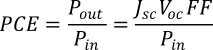
PCE represents the conversion ratio of incident power from light energy to usable electrical power. It is determined by three properties of the solar cell, and one property of the incident spectrum:
- Short circuit current (JSC)
- Open circuit voltage (VOC)
- Fill factor (FF)
- Incident power irradiance (Pin)
JSC, VOC and FF can all be measured directly from an I-V curve measurement. When measuring solar cells, we often refer to current density, J, rather than just the current, I. This is because the amount of current extracted from a solar cell will depend on the size of the active area. By using current density J instead of I, we can compare the device performance of solar cells with different active areas. It is therefore important that you measure the active area of your device (the area that will be illuminated) very precisely, especially when measuring small-area PV devices.
Pin will depend on the solar simulator light source that you use; however, all solar simulators should provide power irradiance of 1 Sun, 100 mW/cm2 or 1000 W/m2 at the device surface. It is therefore important that your solar simulator is correctly calibrated to replicate the solar spectrum accurately.
You can find the JSC, VOC and FF (and subsequently PCE) of your device from a current voltage measurement. This is when you measure the current density running through your device at incremental voltages. This measurement will give you a I-V curve (or more specifically a J-V curve), which will follow the equivalent circuit model of a solar cell.

JSC is the current at which there is zero potential difference across the solar cell. Likewise, VOC is the voltage at which there is zero current flowing through the device. Therefore, you can easily find both JSC and VOC on an IV curve at the y-intercept and the x-intercept respectively. Fill factor is a little more difficult to define - it is a measure of the "squareness" curve. There is a point on the curve where the J and V values are maximized to form the maximum power point (MP). These are called JMP and VMP respectively, and they create a shaded rectangular area of theoretical maximum power available through JMP x VMP. You can then calculate fill factor using the following equation:
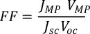
You can find JMP and VMP by working out the point at which J x V is largest. This should be done computationally to ensure that your measurements are consistent.
Solar Simulator

Learn More
 The AM1.5 Spectrum
Solar irradiance varies depending on where you are in the world. This is because of a combination of local atmospheric conditions and geometric considerations.
Read more... I-V Curves: A Guide to Measurement
An I-V curve (short for 'current-voltage characteristic curve'), is a graphical representation of the relationship between the voltage applied across an electrical device and the current flowing through it.
Read more...