Glove Box User Manual
Contents
- Overview
- EU Declaration of Conformity (DoC)
- Safety
- Warning
- Use of Equipment
- Hazard Icons
- General Hazards
- Servicing
- Health and Safety - Installation
- Health and Safety - Servicing
- Unpacking
- Specifications
- System Components
- Installation
- Placement of the Glove Box
- Window Installation
- Glove Box Assembly
- KF Flange Assembly
- Pressure Relief Valve Assembly
- Gas Inlet and Outlet Installation
- Sensor Board Asssembly
- Powering on the System
- Initial Leak Tests
- Threshold Settings and System Purge
- Operation
- Glove Box Diagram
- Glove Box User Interface
- Practical Operation
- Software Operation
- Operational Safety
- Maintenance
- Troubleshooting
1. Overview
A glove box is designed to produce and maintain an inert atmosphere for extended periods of time so that users can work with materials that would otherwise undergo reactions with water or oxygen. This is achieved by using an array of sensors that measure the content of the atmosphere within the system and purging fresh gas through when the pressure becomes too low or the amount of unwanted gas exceeds thresholds set by the user. There is a wide array of applications that glove boxes are used for, both within research and development but also for production. Any situation where the material you are working with may be adversely affected by the presence of oxygen or moisture often requires the use of a glove box. The Ossila glove box is a single station glove box that provides an inert working atmosphere down to 0.5% oxygen and 0.1% relative humidity providing a high degree of protection against moisture and oxygen.
The Ossila Glove Box allows the user to specify the maximum oxygen content, maximum water content, and the range of acceptable over pressure that the system is at. This allows the glove box to automate the process of maintaining the atmosphere by purging fresh inert gas through the system. Equipped with high accuracy oxygen and humidity sensors the system can measure oxygen levels to as low as 0.5% and humidity levels as low as 0.1%. In addition, the system comes with quick purge functionality for quickly removing volatile solvents from the atmosphere; an antechamber transfer routine for simplifying the process of sample transfer in and out of the system; and leak rate testing for ensuring the system is as efficient as possible with gas usage.
Made from high quality low ingress materials such as stainless steel, hardened glass, butyl rubber, PTFE, and Viton. The glove box has extremely low moisture and oxygen ingress rates minimizing the amount of gas required to keep the system in an inert state. These materials also provide excellent chemical resistances while being robust enough for daily use. The glove box also has feed throughs allowing users to equip the systems with services such as power, data lines, and vacuum lines further increasing the functionality of the glove box.
2. EU Declaration of Conformity (DoC)
We
Company Name: Ossila BV
Postal Address: Biopartner 3 Building, Galileiweg 8
Postcode: 2333 BD Leiden
Country: The Netherlands
Telephone Number: +31 (0)718 081020
Email Address: info@ossila.com
declare that the DoC is issued under our sole responsibility and belongs to the following product:
Product: Glove box (L2007A1)
Serial Number: L2007A - xxxx
Object of Declaration
Glove box (L2007A1)
The object of declaration described above is in conformity with the relevant Union harmonization legislation:
EMC Directive 2014/30/EU
RoHS Directive 2011/65/EU
Signed:

Name: Dr James Kingsley
Place: Leiden
Date: 16/11/2021
| Декларация | за съответствие на ЕС |
|---|---|
| Производител | Ossila BV, Biopartner 3 building, Galileiweg 8, 2333 BD Leiden, NL. |
| Декларира с цялата си отговорност, че посоченото оборудване съответства на приложимото законодателство на ЕС за хармонизиране, посочено на предходната(-ите) страница(-и) на настоящия документ. | |
| [Čeština] | Prohlášení o shodě EU |
|---|---|
| Výrobce | Ossila BV, Biopartner 3 building, Galileiweg 8, 2333 BD Leiden, NL. |
| Prohlašujeme na vlastní odpovědnost, že uvedené zařízeni je v souladu s příslušnými harmonizačními předpisy EU uvedenými na předchozích stranách tohoto dokumentu. | |
| [Dansk] | EU-overensstemme lseserklærin g |
|---|---|
| Producent | Ossila BV, Biopartner 3 building, Galileiweg 8, 2333 BD Leiden, NL. |
| Erklærer herved, at vi alene er ansvarlige for, at det nævnte udstyr er i overensstemmelse med den relevante EUharmoniseringslovgivning, der er anført på den/de foregående side(r) i dette dokument. | |
| [Deutsch] | EU-Konformitätserklärung |
|---|---|
| Hersteller | Ossila BV, Biopartner 3 building, Galileiweg 8, 2333 BD Leiden, NL. |
| Wir erklären in alleiniger Verantwortung, dass das aufgeführte Gerät konform mit der relevanten EUHarmonisierungsgesetzgebung auf den vorangegangenen Seiten dieses Dokuments ist. | |
| [Eesti keel] | ELi vastavusavaldus |
|---|---|
| Tootja | Ossila BV, Biopartner 3 building, Galileiweg 8, 2333 BD Leiden, NL. |
| Kinnitame oma ainuvastutusel, et loetletud seadmed on kooskõlas antud dokumendi eelmisel lehelküljel / eelmistel lehekülgedel ära toodud asjaomaste ELi ühtlustamise õigusaktidega. | |
| [Ελληνικά] | Δήλωση πιστότητας ΕΕ |
|---|---|
| Κατασκευαστής | Ossila BV, Biopartner 3 building, Galileiweg 8, 2333 BD Leiden, NL. |
| Δηλώνουμε υπεύθυνα όn ο αναφερόμενος εξοπλισμός συμμορφώνεται με τη σχεnκή νομοθεσία εναρμόνισης της ΕΕ που υπάρχει σnς προηγούμενες σελίδες του παρόντος εγγράφου. | |
| [Español] | Declaración de conformidad UE |
|---|---|
| Fabricante | Ossila BV, Biopartner 3 building, Galileiweg 8, 2333 BD Leiden, NL. |
| Declaramos bajo nuestra única responsabilidad que el siguiente producto se ajusta a la pertinente legislación de armonización de la UE enumerada en las páginas anteriores de este documento. | |
| [Français] | Déclaration de conformité UE |
|---|---|
| Fabricant | Ossila BV, Biopartner 3 building, Galileiweg 8, 2333 BD Leiden, NL. |
| Déclarons sous notre seule responsabilité que le matériel mentionné est conforme à la législation en vigueur de l'UE présentée sur la/les page(s) précédente(s) de ce document. | |
| [Hrvatski] | E.U izjava o sukladnosti |
|---|---|
| Proizvođač | Ossila BV, Biopartner 3 building, Galileiweg 8, 2333 BD Leiden, NL. |
| Izjavljujemo na vlastitu odgovornost da je navedena oprema sukladna s mjerodavnim zakonodavstvom EU-a o usklađivanju koje je navedeno na prethodnoj(nim) stranici(ama) ovoga dokumenta. | |
| [Italiano] | Dichiarazione di conformità UE |
|---|---|
| Produttore | Ossila BV, Biopartner 3 building, Galileiweg 8, 2333 BD Leiden, NL. |
| Si dichiara sotto la propria personale responsabilità che l'apparecchiatura in elenco è conforme alla normativa di armonizzazione UE rilevante indicata nelle pagine precedenti del presente documento. | |
| [Latviešu] | ES atbils tības deklarācija |
|---|---|
| Ražotājs | Ossila BV, Biopartner 3 building, Galileiweg 8, 2333 BD Leiden, NL. |
| Ar pilnu atbilclību paziņojam, ka uzskaitītais aprīkojums atbilst attiecīgajiem ES saskaņošanas tiesību aktiem, kas minēti iepriekšējās šī dokumenta lapās. | |
| [Lietuvių k.] | ES atitikties deklaracija |
|---|---|
| Gamintojas | Ossila BV, Biopartner 3 building, Galileiweg 8, 2333 BD Leiden, NL. |
| atsakingai pareiškia, kad išvardinta įranga atitinka aktualius ES harmonizavimo teisės aktus, nurodytus ankstesniuose šio dokumento | |
| [Magyar] | EU-s megfelelőségi nyilatkozat |
|---|---|
| Gyártó | Ossila BV, Biopartner 3 building, Galileiweg 8, 2333 BD Leiden, NL. |
| Kizárólagos felelösségünk mellett kijelentjük, hogy a felsorolt eszköz megfelel az ezen dokumentum előző oldalán/oldalain található EU-s összehangolt jogszabályok vonatkozó rendelkezéseinek. | |
| [Nederlands] | EU-Conformiteitsverklaring |
|---|---|
| Fabrikant | Ossila BV, Biopartner 3 building, Galileiweg 8, 2333 BD Leiden, NL. |
| Verklaart onder onze uitsluitende verantwoordelijkheid dat de vermelde apparatuur in overeenstemming is met de relevante harmonisatiewetgeving van de EU op de vorige pagina('s) van dit document. | |
| [Norsk] | EU-samsvarserklæ ring |
|---|---|
| Produsent | Ossila BV, Biopartner 3 building, Galileiweg 8, 2333 BD Leiden, NL. |
| Erklærer under vårt eneansvar at utstyret oppført er i overholdelse med relevant EU-harmoniseringslavverk som står på de(n) forrige siden(e) i dette dokumentet. | |
| [Polski] | Deklaracja zgodności Unii Europejskiej |
|---|---|
| Producent | Ossila BV, Biopartner 3 building, Galileiweg 8, 2333 BD Leiden, NL. |
| Oświadczamy na własną odpowiedzialność, że podane urządzenie jest zgodne ze stosownymi przepisami harmonizacyjnymi Unii Europejskiej, które przedstawiono na poprzednich stronach niniejszego dokumentu. | |
| [Por tuguês] | Declaração de Conformidade UE |
|---|---|
| Fabricante | Ossila BV, Biopartner 3 building, Galileiweg 8, 2333 BD Leiden, NL. |
| Declara sob sua exclusiva responsabilidade que o equipamento indicado está em conformidade com a legislação de harmonização relevante da UE mencionada na(s) página(s) anterior(es) deste documento. | |
| [Română] | Declaraţie de conformitate UE |
|---|---|
| Producător | Ossila BV, Biopartner 3 building, Galileiweg 8, 2333 BD Leiden, NL. |
| Declară pe proprie răspundere că echipamentul prezentat este în conformitate cu prevederile legislaţiei UE de armonizare aplicabile prezentate la pagina/paginile anterioare a/ale acestui document. | |
| [Slovensky] | Vyhlásenie o zhode pre EÚ |
|---|---|
| Výrobca | Ossila BV, Biopartner 3 building, Galileiweg 8, 2333 BD Leiden, NL. |
| Na vlastnú zodpovednosť prehlasuje, že uvedené zariadenie je v súlade s príslušnými právnymi predpismi EÚ o harmonizácii uvedenými na predchádzajúcich stranách tohto dokumentu. | |
| [Slovenščina] | Izjava EU o skladnosti |
|---|---|
| Proizvajalec | Ossila BV, Biopartner 3 building, Galileiweg 8, 2333 BD Leiden, NL. |
| s polno odgovornostjo izjavlja, da je navedena oprema skladna z veljavno uskladitveno zakonodajo EU, navedeno na prejšnji strani/prejšnjih straneh tega dokumenta. | |
| [Suomi] | EU-vaatimustenm ukaisuusvakuutus |
|---|---|
| Valmistaja | Ossila BV, Biopartner 3 building, Galileiweg 8, 2333 BD Leiden, NL. |
| Vakuutamme täten olevamme yksin vastuussa siitä, että tässä asiakirjassa luetellut laitteet ovat tämän asiakirjan sivuilla edellisillä sivuilla kuvattujen olennaisten yhdenmukaistamista koskevien EU-säädösten vaatimusten mukaisia. | |
| [Svenska] | EU-försäkran om överensstämmelse |
|---|---|
| Tillverkare | Ossila BV, Biopartner 3 building, Galileiweg 8, 2333 BD Leiden, NL. |
| Vi intygar härmed att den utrustning som förtecknas överensstämmer med relevanta förordningar gällande EUharmonisering som fmns på föregående | |
3. Safety
3.1 Warning
- Only use the 24V power adapter and power cord supplied with the unit.
- Do not use non-inert gasses as an input gas, system is designed for nitrogen use only.
- Do not exceed the maximum input pressure of 4 bar, use a certified regulator valve to reduce pressure before connecting to the system.
- Do not use pressurized gas feedthroughs on KF flanges.
- Do not tamper with or obstruct the pressure relief valves.
- Output of the system should be piped into a vented fume hood or ventilation stack.
- Do not use in an enclosed space, minimum room volume of 30 m3 recommended.
- Users should follow scheduled maintenance outlined in the user manual to ensure efficient and safe operation of the system.
- If using solvents and chemicals, users are expected to be trained in their usage and carry out a COSHH risk assessment. Frequent purges of the system should be done when using solvents to flush the system.
3.2 Use of Equipment
This glove box is designed to be used as instructed, it is intended to be used under the following conditions:
- Indoors in a laboratory environment (pollution degree 2).
- Altitudes up to 2000 m.
- Temperatures of 5°C to 40°C; maximum relative humidity of 80% up to 31°C.
3.3 Hazard Icons
The following symbols can be found at various points throughout this manual. Note and read each warning before attempting any associated operations associated with it:
Table 3.1 Hazard warning labels used in this manual.
| Symbol | Associated Hazard |
|---|---|
 |
General warning or caution, which accompanying text will explain |
 |
Electrical shock |
 |
Pinch point |
 |
Risk of explosion |
 |
Risk of asphyxiation |
3.4 General Hazards
Before installing or operating the glove box, there are several health and safety precautions which must be followed and executed to ensure safe installation and operation.
WARNING: Improper handling when operating or servicing this equipment can result in serious injury or death. Read this manual before operating or servicing this equipment.
Emergency power disconnect options: Use the power cord as a disconnecting method and remove it from the power source. To facilitate disconnect, make sure the power outlet for this cord is readily accessible to the operator.
3.5 Servicing
If servicing is required, please return the unit to Ossila Ltd. The warranty will be invalidated if:
- Modification or service has taken place by anyone other than an Ossila engineer.
- The Unit has been subjected to chemical damage through improper use.
- The Unit has been operated outside the usage parameters stated in the user documentation associated with the Unit.
- The Unit has been rendered inoperable through accident, misuse, contamination, improper maintenance, modification, or other external causes.
3.6 Health and Safety - Installation
|
Heavy object. To avoid muscle strain or back injury either use lifting aids or multiple people to move the glove box to the location of installation. |
|
Pinch point. When moving the equipment be careful to avoid pinching hazards when lowering. Make sure all fingers and hands are clear of the object before releasing. |
|
Risk of explosion. Maximum input pressure of 4 bar. When installing the system, the use of a certified pressure regulation valve is required. |
|
Risk of explosion. Connect only inert gas to the glove box, the use of other gasses may present a risk of fire or explosion. The system is designed for nitrogen use only. |
|
Risk of asphyxiation. Improper installation of system may result in the formation of an asphyxiant atmosphere. Ensure input is at correct pressure and that connections are leak free. Output should be piped into a vented fume hood or a ventilation stack. Minimum room size of 30 m3 with a minimum of 4 air changes per hour is recommended. |
3.7 Health and Safety - Servicing

Servicing beyond the replacement of standard components listed in the servicing section should only be performed by an Ossila engineer. Any modification or alteration may damage the equipment, cause injury, or death. It will also void your equipment’s warranty.
4. Unpacking
4.1 Packing List
The items included with the Ossila Glove Box are:
- Glove Box assembly
- Glass viewing window assembly pack:
- 1 x 6 mm glass pane
- 2 x Window gaskets
- 1 x Window frame
- 1 x Pack of domed nuts
- 1 x LED assembly
- Glove port assembly pack:
- 2 x Butyl rubber gloves
- 2 x Rubber rim guard
- 2 x O-rings
- Pressure relief valve assembly pack:
- 1 x Pressure relief valve
- 2 x Sensor boards
- Power cord set (specific for country of operation)
- User guide manual
4.2 Damage Inspection
Examine the components for any evidence of shipping damage. If damage has occurred, please contact Ossila directly for further action.
5. Specifications
The glove box specifications are shown in Table 5.1, Table 5.2, and Table 5.3.
Table 5.1 Glove Box Specifications
| External Dimensions |
Width: 750 mm Height: 600 mm Depth: 550 mm |
|---|---|
| Internal Dimensions |
Width: 600 mm Height: 600 mm Depth: 500 mm |
| Antechamber Internal Dimensions |
Width: 150 mm Height: 150 mm Depth: 150 mm |
| Box and Antechamber Material | 2 mm, Grade 304 Stainless Steel, 2B Surface Finish |
| Window Material | 6 mm, Hardened Glass |
| Gloves | 2 x Butyl Rubber Gloves, 10 Inch Diameter |
| Feedthroughs | 2 x DN 40 ISO-KF Blanked Feedthroughs |
| Gas Inlet/Exhaust | 12 mm Push-Fit Connector (PTFE Recommended) |
| Maximum Input Pressure | 4 bar |
| Working Overpressure Range | 0 mbar to 5 mbar |
| Purge Overpressure Range | 10 mbar to 15 mbar |
| Leak Rate | < 0.25% Vol/hour (ISO Class II) |
| Lighting | 9 W White Light LED |
| Power Supply |
Input: 100 V – 230 V; 50 Hz / 60 Hz; 50 VA Output: 24 V DC, 2.0 A |
| Weight | 40 kg |
Table 5.2 Glove Box Sensor Board Specifications
| Oxygen Sensor Range | 0.5 % to 25 % |
|---|---|
| Oxygen Sensor Precision | 0.01 % |
| Moisture Sensor Range | 5°C to 40°C; Up to 80% RH @ 31°C |
| Moisture Sensor Precision | 0.1 % Relative Humidity (15 PPM) |
| Pressure Sensor Range | 300 mbar to 1200 mbar |
| Pressure Sensor Precision | 0.005 mbar |
| Temperature Sensor Range | 0 °C to 65°C |
| Temperature Sensor Precision | 0.1 °C |
Table 5.3 Glove Box Software Specifications
| Oxygen Units | % Content |
|---|---|
| Moisture Units | Relative Humidity |
| Oxygen Set Point | Oxygen value above which purging is triggered |
| Moisture Set Point | Moisture value above which purging is triggered |
| Minimum Overpressure | Minimum overpressure before input opened |
| Maximum Overpressure | Maximum overpressure before exhaust opened |
| Maximum Purge Pressure | Maximum pressure that the system will go to whilst purging |
| Glove box Settings | UI for changing the set point and overpressure values for the system |
| Monitor Main Chamber | UI for monitoring the stats inside the main chamber |
| Monitor Antechamber | UI for monitoring the stats inside the antechamber |
| Quick Purge Options | 30 s, 60 s, 120 s |
| Leak Test | Performs a leak test on the system |
| Alarm | Sounds when values are outside of set range for an extended period |
| Alarm Mute | Temporary mute the alarm for 60 s |
6. System Components
The Ossila Glove Box comes with the following components:
- Glove box unit
- Power supply cord and power supply
- Window Assembly Pack
- Glove Port Assembly Pack
- KF Flange Pack
- Pressure Relief Valve Pack
- Sensor Board Pack
7. Installation
The process for installing the glove box is as follows:
- Locate a suitable position to install the glove box.
- Unpack the system.
- Install the window and seals.
- Install the gloves.
- Install the KF Flanges.
- Install the pressure relief valve.
- Connect the gas inlet and vent line.
- Install the sensor boards.
- Turn the system on.
- Perform initial leak test.
- Set oxygen and humidity thresholds.
- Wait for system to reach desired conditions.
7.1 Placement of the Glove Box
- Remove all the contents from inside the glove box.
- Place the anti-slip mat onto the surface you wish to place the glove box. The surface should be level, flat and at an appropriate height for users to use comfortably.
- With the help of one or more additional people lift the glove box and place it on top of the anti-slip mat.
7.2 Window Installation
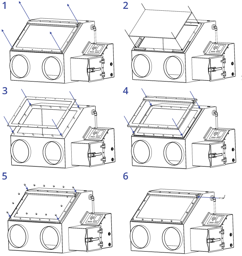
Inside the Ossila box there should be a rubber gasket, and a bag of 12 M6 domed nuts. Underneath the Ossila box wrapped in bubble wrap is a 6 mm thick glass panel. Following the instructions below and the Figure 7.1 install the window.
- Unscrew the four domed nuts on the corners of the metal frame attached to the front of the box. Remove the frame.
- Place the window on top of the foam gasket using the L spacers provided to align it.
- Taking the rubber gasket place it around the window opening of the glove box making sure to put the standoffs through the designated holes in the gasket.
- Place the metal frame on top and ensure all the standoffs go through the frame.
- Using the domed nuts fasten each by hand until every nut is tightened. Using a wrench tighten each nut a little bit at a time. Ensuring the frame provides an even pressure on the glass panel. Once the metal frame is in contact with the metal box do not tighten any more, doing so may damage the box.
- Take the power cord coming from the electronics case and plug it into the light strip.
7.3 Glove Box Assembly
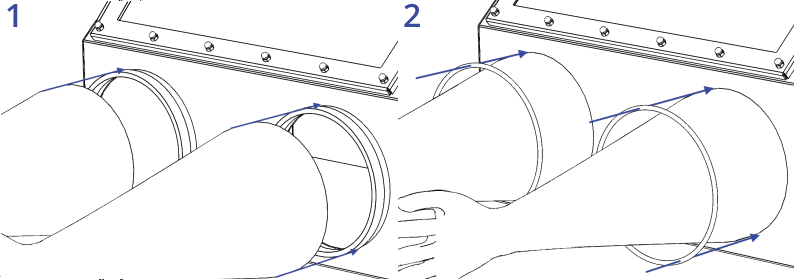
Inside the box there should be a pair of butyl gloves, and 4 O-rings. Following the instructions below and Figure 7.2 install the gloves.
- Place the gloves onto the glove ports ensuring the rubber ring of the sleeve is flush against the front wall of the glove box.
- Place two O-rings over the top of the gloves
7.4 KF Flange Assembly
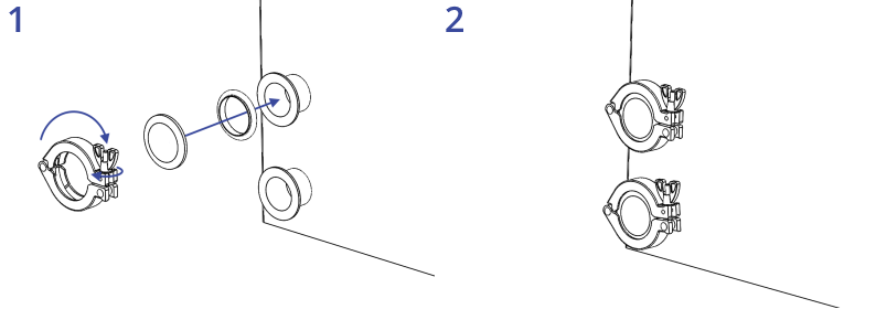
Taking the bags containing the KF flanges unpack the contents, there should be 2 centering rings, 2 blanking flanges, and 2 hinge clamps. Following the instructions below and Figure 7.3 install the KF flanges.
- Sit the centering ring onto the flange nipple.
- Place the blanking plate over the centering ring.
- Close the hinge clamp around the flange, spacer, and blanking plate. Tighten the nut until a tight seal is formed between the O-ring and the surfaces.
- Repeat for the second flange.
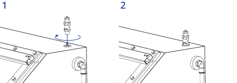
7.5 Pressure Relief Valve Assembly
Taking the bag containing the pressure relief valve and unpack the contents. There should be a single pressure relief valve and a Dowty washer. Following the instructions below and Figure 7.4 install the pressure relief valve:
- Ensure that the washer supplied is seated on the threaded end of the pressure relief valve and insert it into the threaded hole on the top of the unit.
- Tighten the pressure relief valve using a wrench, use the bottom nut for tightening the relief valve.
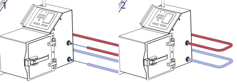
7.6 Gas Inlet and Outlet Installation
On the side of the right side of the unit there are two bulk-head feedthroughs into the electronics case. These are for the gas input and the output of the system. To correctly install the system, you will need 12 mm piping, ideally this should be rated for handling gasses at high pressures and have low rates of moisture and oxygen ingress. We recommended either a metal pipe or a PTFE pipe for this, use of other pipes may result in ingress of moisture into the feed line over time compromising performance of the glove box. Following the instructions below and Figure 7.5 install the gas and outlet pipes:
- Using a 12 mm diameter pipe connect the input to the upper bulkhead feedthrough, the input should be down regulated to approximately 2 bar before entering the system.
- Depending upon the length of piping required for the exhaust you may need to use the adapters provided to connect to a wider diameter hose. For exhaust lengths of 1m or lower we recommend a 12mm diameter pipe, for 1 m to 3 m a 16 mm diameter pipe, while for distances of 3 m or more we recommend a 25 mm diameter pipe.
- Using the appropriate connector and diameter pipe connect the output to the lower bulkhead feedthrough. The output should be piped into a vented fume hood or directly into a ventilation stack.
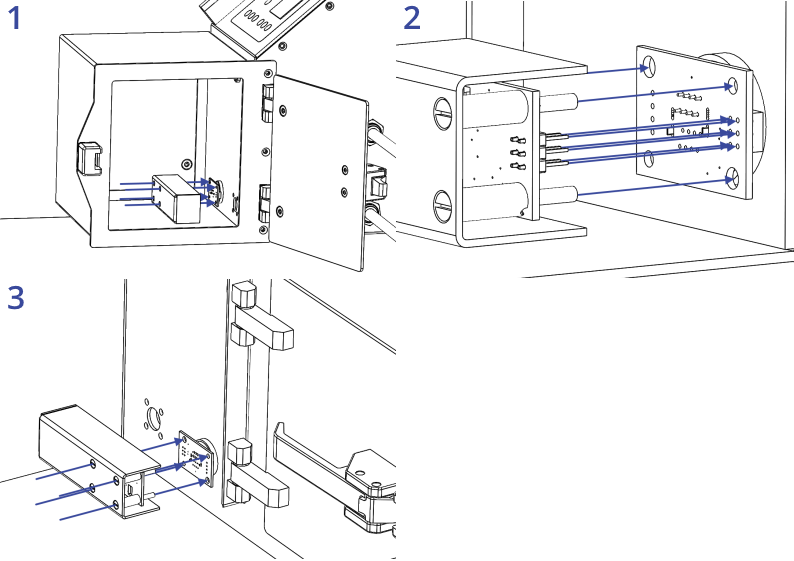
7.7 Sensor Board Asssembly
On the inside of the antechamber on the back wall and in the main chamber at the bottom right there should be two feedthroughs with printed circuit boards attached. These are for connecting the sensor boards to. Taking the bag labeled sensor boards unpack the contents. There should be two sensor board assemblies. Following the instructions below and in Figure 7.6 install the sensor boards:
- Opening the antechamber push the sensor board into the connection board.
- The sensor board has four alignment legs which will fit into the holes in the corners of the connection board. Using these legs as guides ensure that the six pins highlighted slot into the header on the connector board.
- Inside the main chamber push the second sensor board into the connection board. Just like in the antechamber the alignment legs can be used to help guide the board into place.
7.8 Powering on the System
An AC/DC power adapter will be provided with the unit alongside a power cord that is appropriate for the country being shipped to. Once the previous assembly steps have been taken the power adapter can be plugged into the wall socket and then into the DC power jackat the rear of the system. The power switch should then be turned from 0 to 1 on the back to turn on the unit.
7.9 Initial Leak Tests
When the system powers up the user must enter the time and date values. After this is complete it will go to the glove box status page. When a system is first installed it is advised to perform a leak test to ensure that the system is performing to acceptable levels and that there are no leaks that could cause excessive gas usage. Upon starting the leak test the overpressure will increase to a set level. The overpressure is monitored over a set period to see how much the value drops by. If during this testing the pressure drops below 0.25% there is likely a leak within the system and testing for the source of the leak should begin immediately. Otherwise, the user should wait for the results of the test to be complete.
Over the testing period the ideal range of pressure drop for the system is between (-0.0005 and -0.0025 per hour) if the pressure drop is in this region then the leak test is successful, and the system is holding pressure. In the range of (-0.0025 and -0.005) there is a minor leak present that should be addressed. If the pressure change is greater than -0.005 this indicates that there are several minor leaks or a major leak. To help find leaks within the system a leak detector fluid should be used, alternatively a combination of water and a surfactant (such as dishwashing soap) can be used.
Spraying small amounts of leak detector fluid near gaskets and O-rings check to see if there is any bubbling of the fluid that could indicate a leak. If bubbling occurs, try applying more pressure to the seal by tightening any screws or nuts. If this does not help, remove the seal, and clean the area taking care to ensure no debris falls onto the seal such as hairs or fibers. Repeat until no more bubbles are showing.
Once all seals are checked and no more bubbling is visible repeat the leak test and ensure that it is within the ideal range.
7.10 Threshold Settings and System Purge
Once the system has reached the desired range of leak rate the set point values for oxygen, humidity, and over pressure should be set. To begin with open the menu and navigate to the pressure parameters page within the main menu and set the over pressure parameters. We recommend setting the lower limit at 0 mbar, the upper limit at 5 mbar. These will be the minimum and maximum values the system will allow the pressure to get. The lower hysteresis limit we recommend to set to 1mbar and the upper to 2 mbar. This should give a good balance between the working pressures, the frequency of gas inlet and the amount of gas lost when moving hands into and out of the glove box.
Once the pressure parameters have been set press the settings button, here set the oxygen and moisture set points along with the target pressure. These should be set based upon what you want to use the system for and the maximum allowed oxygen and moisture that you can allow, it should be noted that the lower the set point values are the more frequent the system will purge and the higher the gas usage will be. We would recommend a set pressure of 2 mbar. Along with the hysteresis limits set earlier this would let the system operate between 1 mbar and 4 mbar without purging or venting. When these have been set press the purge button and the system will begin to purge.
Once the system begins to purge it will continue to do this till the target oxygen and moisture values are reached, the pressure in the chamber at this point will be too high for a user to begin working in the system. The glove box should therefore be left alone until the purging has finished, the time required to go from a system at atmosphere to the lowest set point possible is around 20 minutes and should use up around 0.5 m3 of gas. Once the glove box has finished purging the pressure should drop to within the working pressure range used within the settings.
Upon first starting the system it is likely there will be outgassing of moisture over time, this will see the moisture levels increase quickly and the glove box will undergo frequent short purges to get it below the set threshold again. This can take a few hours till the system is fully settled and the system is fully outgassed.
8. Operating the Glove Box
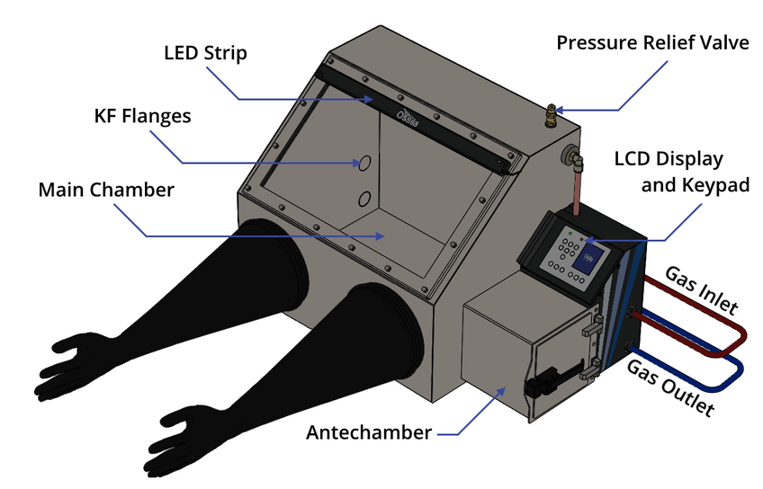
8.1 Glove Box Diagram
An isometric view of the glove box is shown in Figure 8.1, with all the relevant components highlighted.
8.2 Glove Box User Interface
Figure 8.2 shows the front panel of the glove box, where the function of each of the keypad buttons is explained in Table 8.1.
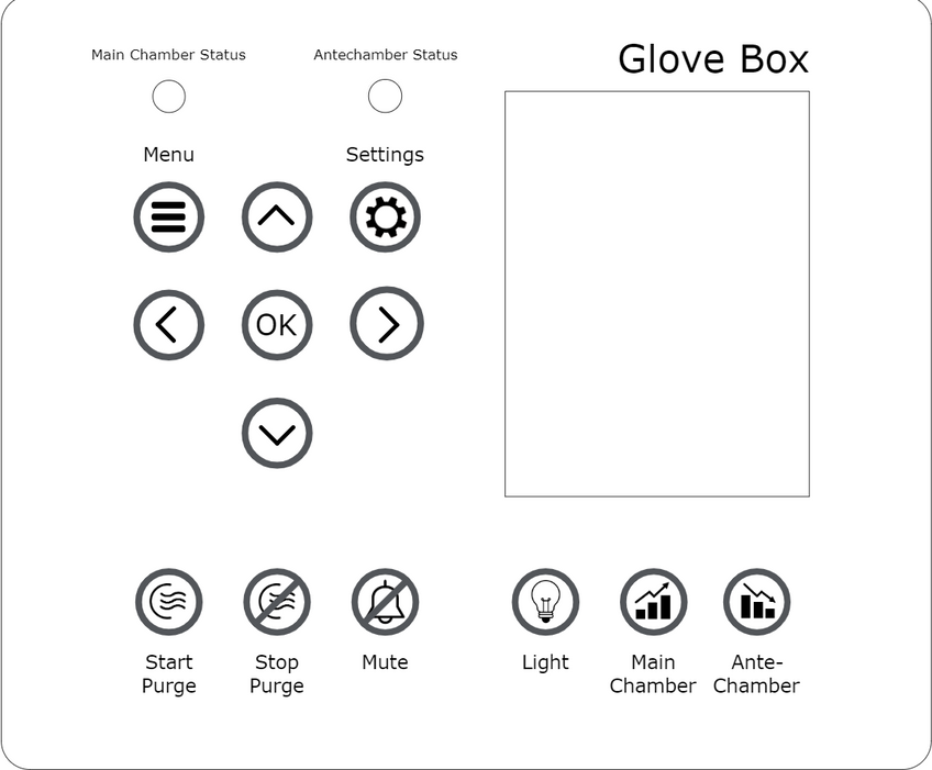
Table 8.1 Operational buttons and their associated functions
| Button | Function |
|---|---|
 |
Navigating ‘up’ through menus; increasing selected values by 1; cycling through options |
 |
Navigating ‘down’ through menus; decreasing selected values by 1; cycling through options |
 |
Navigating ‘right’ through menus |
 |
Navigating ‘left’ through menus |
 |
Press to select, edit, or accept changes |
 |
Toggle the lights on and off |
 |
Temporarily mute the alarm for 30 seconds |
 |
Quick purge; purges the system for a short period of time |
 |
Stop purge; stops the quick purge of the system |
 |
Enters the main menu. Allows the navigation to diagnostic tests, settings, system information, and other options |
 |
Enters the configuration menu. Here set point values can be set for the oxygen content, water content, and maximum and minimum operating pressures |
 |
Enters the main chamber statistics screen. Shows information such as pressure, temperature, oxygen content, and water content in the main chamber |
 |
Enters the antechamber statistics screen. Shows information such as pressure, temperature, oxygen content, and water content in the antechamber |
8.3 Practical Operation
When using the glove box there are several things that should be taken into consideration to ensure that the atmosphere inside the glove box remains inert, and that excessive gas consumption does not occur.
8.3.1 Sample Transfer Protocol
The most likely time when the glove box chamber can be exposed to atmosphere is when moving samples in and out of the glove box through the antechamber. The internal door between the main chamber and antechamber should only be opened when the antechamber itself is filled with inert gas. To ensure that this happens it is useful to follow a standard process when opening the internal door. With the Ossila Glove Box the process becomes easier as there are sensors available to measure the condition of the air inside the chamber.
We recommend following the procedure outline below when moving samples into the glove box:
- Check that the internal door between the main chamber and antechamber is closed.
- Check that the antechamber is currently not purging.
- Open the outside door and place samples into the chamber.
- Close the outside door.
- Using the transfer process in the software purge the antechamber.
- Wait until the software says it is OK to continue.
- Open the internal door and remove the samples.
- Close the internal door.
We recommend following the procedure outlined below when taking samples out of the glove box:
- Check that the external door of the antechamber is closed.
- Using the transfer process in the software purge the antechamber.
- Wait until the software says it is OK to continue.
- Open the internal door and place the samples into the chamber.
- Close the internal door.
- Open the external door and remove the samples.
- Close the external door.
8.4 Software Operation
8.4.1 Glove Box Start Up
- Switch ON (position ‘1’) the Ossila Glove Box power switch. The Ossila splash screen will be displayed for a few seconds before transitioning to the next screen.
- On start up the system will require the user to input the date / time information along with the desired system set points.
8.4.2 Glove Box Status Page
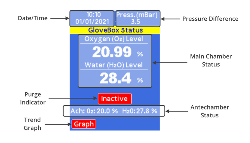
The glove box status page can be accessed by pressing the status page button, on this screen the following information can be seen:
- The date and time.
- The pressure difference.
- The current moisture and humidity levels in the chamber.
- The humidity and oxygen levels in the antechamber.
In addition, the page has an indicator to highlight if the main chamber is currently actively purging, this will toggle between a red ‘inactive’ indicator to a green ‘active’ one if purging is occurring. There is also the option to view the oxygen, humidity, and pressure values over time within the trend graph window. To access this trend graph, use the navigation keys to select the graph button and press “OK”. While this page is selected activating the purge button on the keypad will begin a purge of the main chamber bringing it down to the set values indicated.
8.4.3 Antechamber Status Page
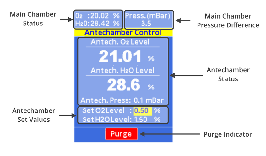
The antechamber status page can be accessed by pressing the antechamber status page button, on this screen the following information can be seen:
- Main Chamber Status
- Main Chamber Pressure Difference
- Antechamber Status
- Antechamber Set Values
In addition, the page has an indicator to highlight if the antechamber is currently actively purging. This will toggle between an inactive red ‘purge’ indicator and an active green ‘purge’ indicator. While this page is selected activating the purge button on the keypad will begin a purge of the antechamber bringing it down to the set values indicated.
8.4.4 Configuration Page
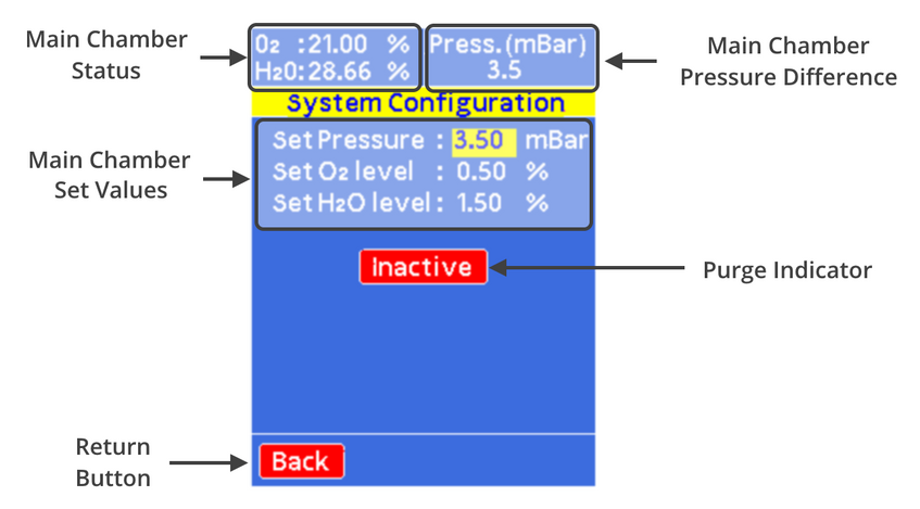
The configuration page allows the user to quickly set control points for the overpressure, oxygen levels, and humidity levels. It can be accessed by pressing the configuration page button or via the menu, on this screen the following information can be seen:
- Main Chamber Status
- Main Chamber Pressure Difference
- Main Chamber Set Values
To modify the set values, use the navigation arrows to highlight (in yellow) the value you wish to edit. By pressing “OK” this will allow you to edit the value, you can use the “Left” or “Right” buttons to move what significant digit you wish to change and the “Up” or “Down” buttons to increase or decrease this value. To confirm the changes to the value, press “OK”.
In addition, the page has an indicator to highlight if the chamber is currently actively purging. This will toggle between an inactive red ‘inactive’ indicator and an active green ‘active’ indicator. There is also a back button that will allow you to navigate back to the menu page. While this page is selected activating the purge button on the keypad will begin a purge of the main chamber bringing it down to the set values indicated.
8.4.5 Menu Page
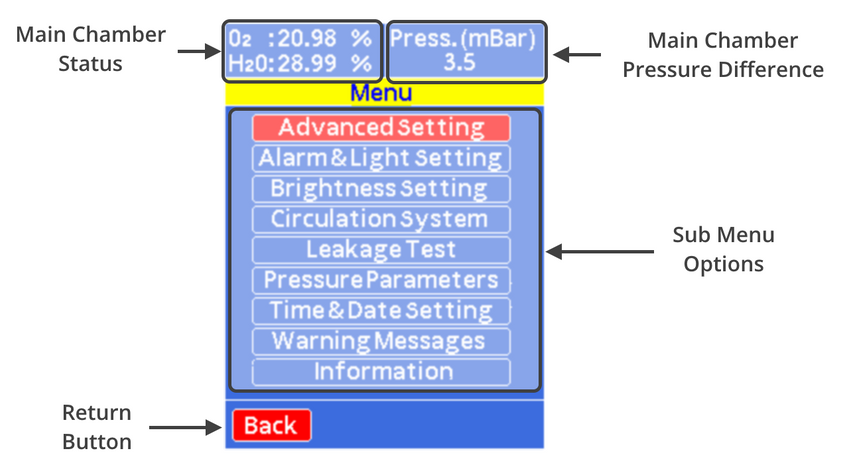
The menu page allows the user to navigate to a series of different options available within the software. It can be accessed by pressing the menu button. On this screen the following information can be seen:
- Main Chamber Status
- Main Chamber Pressure Difference
- Sub Menu Options
The options for the sub menu contain the following functionality:
- Advanced Settings: All sensor data, sensor analysis, print sensor data, USB settings, clear stored data, and restore factory default settings.
- Alarm and Light Settings: Turn on/off the alarm, set box light to auto or manual.
- Brightness Settings: Change screen brightness.
- Circulation System: Set a short purge of system for a specific time.
- Leakage Test: Set leakage test settings and start leakage test.
- Pressure Parameters: Advanced overpressure settings with upper limit, lower limit, and hysteresis values.
- Time and Date Settings: Update time and date of the system.
- Warning Messages: Log of previous warning messages and time they occurred.
- Information: Manufacturer’s information
8.4.6 Sub Menu Pages
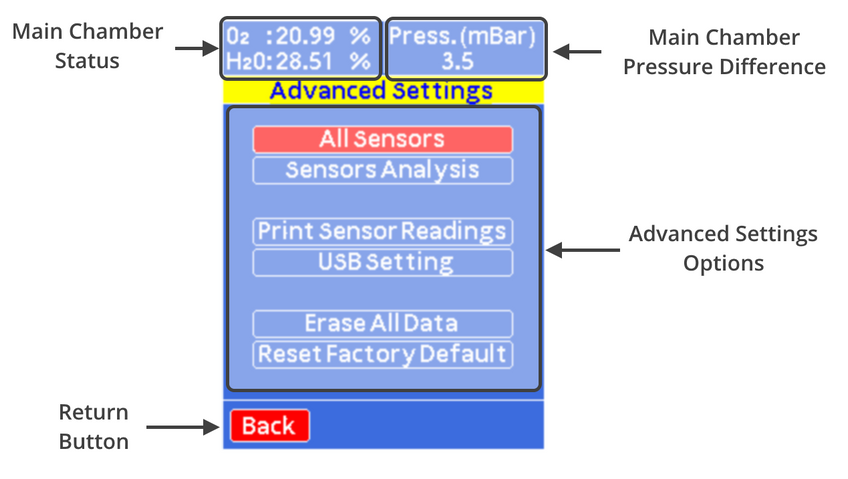
The advanced settings page gives users access to additional information and options.
- All Sensors: Provides raw data reading from all sensors including internal/external pressure, temperature, oxygen, and humidity.
- Sensor Analysis: Performs checks on the sensors and analyzes data over time to check on integrity of sensors and to see if they need replacing.
- Print Sensor Readings: Prints sensor data to USB as a string of comma delimited data.
- USB Setting: Update settings of USB for printing data and updating firmware.
- Erase All Data: Erases currently logged sensor data that is stored on the system.
- Reset Factory Defaults: Resets software settings to the original factory default values.
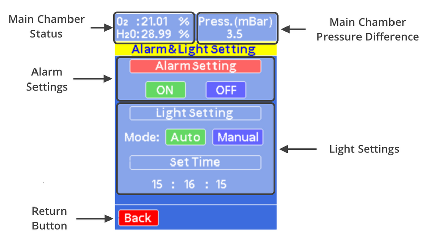
The alarm and light settings page allow you to change some of the default settings for the alarm and internal light of the glove box:
- Alarm Settings: Set the alarm to have an audible alarm or not to alert users of warnings from the system.
- Light Settings: Set the light to turn off automatically at a specific time or set the light to manual.
- Set Time: Set the time that the light turns off automatically
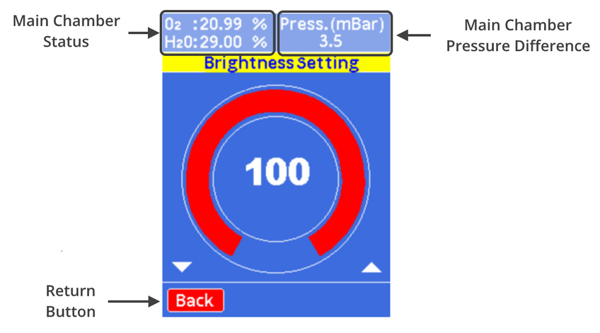
The brightness settings allow the user to change the screen brightness on the display. To do this use the “Left” navigation button to decrease the value or the “Right” navigation button to increase the value.
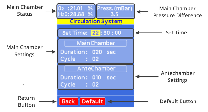
The circulation system settings allow users to set the chamber to undergo a short purge to provide air movement in the chamber during times where air movement may be reduced, such as overnight. We recommend setting a short circulation cycle early in the morning before working in the system, by providing air movement in the system it helps to disrupt pockets of air that form and help give a more accurate indication of the atmospheric condition in the box. This can also be useful when outgassing items overnight in the antechamber
- Set Time: Allows the user to set the time of when the short circulation occurs.
- Main Chamber Settings: Here the length of each purge and the number of times it occurs can be adjusted. We recommend several short purges to create as much air flow as possible.
- Antechamber Settings: Just like the main chamber the antechamber can be cycled to create air flow. Here the duration and number of purge cycles can be adjusted.
- Default Button: Returns the settings to the default values used in the factory settings.
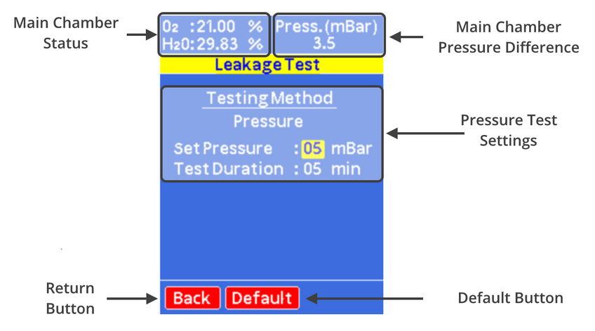
The leakage test page allows users to test the leak rate of the system using a pressure drop test. Here the system will increase the pressure difference to a value set by the user and measure the pressure drop for a set time. At the end of the test, it will display a leak rate for the chamber. The pressure test will not begin until the internal temperature value becomes constant. The reason for this is that the chamber temperature sees a drop when the chamber pressure is increased. While the temperature returns to an equilibrium value this will cause further pressure changes not related to the leak rate of the chamber.
- Pressure Test Settings: Allows the user to set the over pressure during the test and the maximum test duration.
- Default Button: Returns the set pressure value and test duration to their default values.
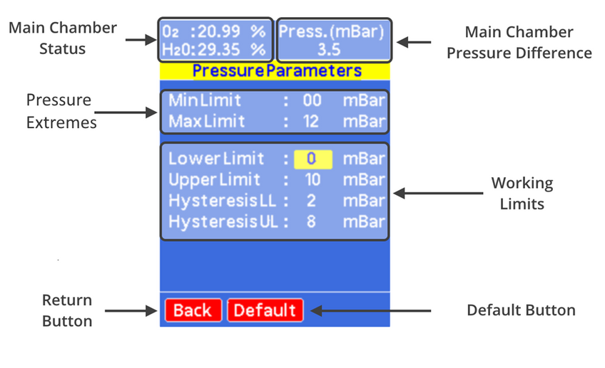
The pressure parameters page allows the user to set advanced pressure settings. These include the purge pressure limits and the working limits. The working limit allows control of the hysteresis values for the upper and lower limits.
- Pressure Extremes: Hardware limits where the system will either purge if the pressure will go below the minimum and where the gas inlet will be closed if the max value is exceeded. These values are what used during the purge process.
- Working Limits: The pressure limits during normal operation can be set here. The hysteresis lower limit is the acceptable pressure drop from the target pressure that the system will depressurize to upon opening of exhaust valve. The hysteresis upper limit is the pressure value the system will purge to above the set point. While the upper and lower limits are the values at which the system will begin venting or purging if they exceed.
- Default Button: Returns the pressure values to the default settings.
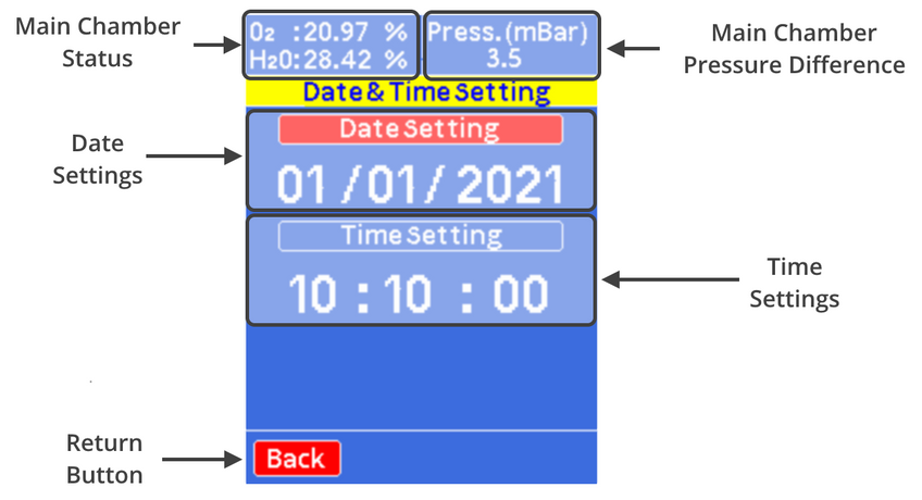
The time and date page allows users to set the time and date of the system clock to their local time.
- Date Settings: Allows the user to set the current days date.
- Time Settings: Allows the user to set the current time.
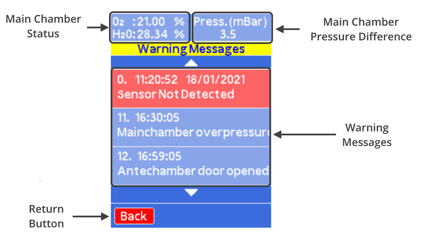
The warnings page has all the unread warnings that have occurred, these are time and date stamped so that the user can correlate it with working patterns within the glove box to help identify the reason for specific warning occurring. The warnings can be removed by navigating to a specific warning and pressing the “OK” button, this will delete them from memory. The warnings can be scrolled through using the “Up” or “Down” buttons.
8.5 Operational Safety
Any procedure that is done with the dip coater should be carried out with a suitable operating procedure, risk assessment, and COSHH forms to ensure that the user knows and understands the potential hazards inherent to the system of work they are undertaking. The following are safety points that should be noted by the user before any procedure is undertaken with the glove box.
8.5.1 High Pressure System
The glove box when operated within the range of pressures indicated within the manual poses very little danger. Input pressures should be operated at the ideal pressure of 2 bar. Higher pressure values pose a significant danger as connection, and valves are not designed to operate at pressures above those stated. Using higher pressure inputs could result in significant leaks of inert gas or pressurization of chambers beyond what they are designed for.
Pressurized gas inputs should never be connected via the KF-Flanges, pressure relief valves installed within the system have a maximum flow rate that can be vented. The connection of a pressurized gas line via the KF flanges could result in an inflow of gas at a rate higher than the pressure relief valve can vent at. Resulting in over pressurizing of the system and significant damage to the system and installation, along with potential harm to users.
8.5.2 Use of Asphyxiant
The glove box requires the use of an inert gas to function as intended. Although the box is designed to ensure that inert gasses are maintained within the system and are expelled through an exhaust pipe the presence of leaks or damage to the box could result in the release of gas from the system. It is advised that the minimum room size that the system should be used within is 28.8 m3, however it is recommended that when working with inert gasses that an oxygen monitor is present to check that the workspace is safe to use.
9. Maintenance
9.1 Cleaning
Cleaning inside of the system should be done with care to ensure that the environment in the chamber is not compromised. The use of dry lint free cloths is recommended, if solvents are required to clean ensure that there is no residual water content in the solvents and that the solvents are used sparingly. If solvents are used the system should be purged afterwards to ensure any residual solvent is removed from the system.
9.2 System Purging
If solvents are used within the glove box, the system should be purged for a short period of time to help remove any build-up of solvents. Excess solvent within the system can result in damage to the sensor board reducing its operational lifetime. In addition, excess solvent within the system can remain for long periods of time and affect experiment results and damage materials and samples stored within the glove box.
9.3 Glove Replacement
Glove should be checked for damage regularly. If punctures occur within the gloves the systems leak rate will increase significantly and there is potential for moisture and oxygen ingress to occur. If damage occurs the gloves should be replaced, the recommended port diameter of the system is 10 inches. It is recommended that the gloves should be made from butyl rubber due to the low ingress rates of moisture and oxygen. To replace the gloves without exposing the system to atmosphere follow these steps:
- Push the glove that is to be replaced into the box.
- Remove the O-Ring that is closest to the main chamber.
- Roll back the glove onto the second outer O-ring. Please take care not to let the glove come off the port completely.
- Compress the new glove as much as possible to remove excess air.
- Place the new glove over the glove port, over the old glove.
- Install the O-ring closest to the main chamber onto the glove port, over the new glove.
- Using the other glove, remove the old glove pulling it into the glove box.
- Install the outer O-ring onto the glove port, over the new glove.
- Remove the old glove from the box via the Antechamber.
9.4 Oxygen Sensor Replacement
The oxygen sensors used within the system needs replacing once every 6 - 12 months, this is dependent upon exposure to moisture and solvents. Replacements can be purchased directly from Ossila. To replace the sensor, follow these instructions:
- Unscrew the two domed screw on the sensor board cover.
- Remove the sensor board from the chamber.
- Detach the senor board from the sensor board cover.
- Gently pull on the oxygen sensor, it should detach from the sensor board.
- While wearing gloves push in the new oxygen sensor and reattach the board to the sensor cover.
- Reconnect the sensor to the feedthrough and screw it in place to secure it.
10. Glove Box Troubleshooting
| Problem | Possible Cause | Action |
|---|---|---|
| No power/display | The power switch on the unit is in the OFF position | Check the connection and ensure the power is turned ON |
| The power supply may not be connected properly | Ensure the unit is firmly plugged in to the power supply, and the plug is firmly connected to both the adapter and the working power socket | |
| The fuse on the rear panel has blown | Ensure the unit is unplugged. Check the fuse on the rear panel. If it has blown, replace with a suitably rated 1A slow blow fuse | |
| The power supply adapter has a fault | Contact Ossila for a replacement power supply adapter | |
| No obvious cause | If all the above causes have been considered, there may be a fault on the board. Please contact Ossila for information | |
| High Gas Usage | Leak present in the chamber |
|
| Check set points | Check to see what set points are causing the system to top up with inert gas. If the lower pressure limit is being reached there is likely a leak. If the oxygen or humidity set points are being reached then there may be outgassing or ingress. If no set points are being triggered it could be a leak in the delivery line. |