Spin Coating: Complete Guide to Theory and Techniques

Spin coating is a common technique for applying thin films to substrates. When a solution of a material and a solvent is spun at high speeds using a spin coater, the centripetal force and the surface tension of the liquid together create an even covering. After any remaining solvent has evaporated, spin coating results in a thin film ranging from a few nanometres to a few microns in thickness.
Spin coating is used in a wide variety of industries and technology sectors. Its primary advantage of spin coating over other methods is its ability to quickly and easily produce very uniform films.
The use of spin coating in organic electronics and nanotechnology is widespread and has built upon many of the techniques used in other semiconductor industries. The relatively thin films and high uniformity required for effective device preparation, as well as the need for self-assembly and organization to occur during the casting process, do however necessitate some differences in method.
This guide aims to introduce general spin coating concepts, cover spin coating equations and theory, and describe some of the specific techniques useful in organic electronics and nanotechnology.
Contents
- Introduction to Spin Coating
- Quickstart Guide (Video)
- Spin Coating Theory
- Choosing a Spin Coating Method
- Practical Spin Coating Tips
- Special Requirements for Spin Coating Nanoparticles
- Spin Coating Small Substrates and Wafer Fragments
- Automated Dispensing
- Ultra-low Spin Speeds and Covered Drying
- Spin Coating with Solvent Blends
- Visible Assessment of Drying and Film Uniformity
- Ambient Conditions and Changes in Drying Time
- Spin Cleaning and Wash Steps
- Preventing Common Defects
- Two Step Spin Coating and Bead Removal
- Avoiding a Hole in Middle of Film
- Avoiding Vacuum Warping of Substrate
- Spin Coating Low Viscosity Solvents
- Incomplete Coating of Substrate
- Pin Holes and Comet Streaks
- Aggregation and Filtration
- Coating Difficult Solutions
- Solutions with Poor Solubility
- Solutions with Extreme Volatility
- Poorly-Wetting Solutions
- Viscous and Non-Newtonian Solutions
- References and Further Reading
Introduction to Spin Coating
Spin coating generally involves the application of a thin film (a few nm to a few um) evenly across the surface of a substrate by coating (casting) a solution of the desired material in a solvent (an "ink") while it is rotating. Put simply, a liquid solution is deposited onto a spinning substrate in order to produce a thin film of solid material, such as a polymer.
The rotation of the substrate at high speed (usually >10 rotations per second = 600 rpm) means that the centripetal force combined with the surface tension of the solution pulls the liquid coating into an even covering. During this time the solvent then evaporates to leave the desired material on the substrate in an even covering.

This process can be broadly divided into 4 main steps:
- Deposition
- Spin up.
- Spin off
- Evaporation
In the initial step, the solution is cast onto the substrate, typically using a pipette. Whether the substrate is already spinning (dynamic spin coating) or is spun after deposition (static spin coating), the centrifugal motion will spread the solution across the substrate.
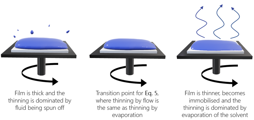
The substrate then reaches the desired rotation speed – either immediately or following a lower-speed spreading step. At this stage, most of the solution is expelled from the substrate. Initially, the fluid may be spinning at a different rate than the substrate, but eventually the rotation speeds will match up when drag balances rotational accelerations – leading to the fluid becoming level.
The fluid now begins to thin, as it is dominated by viscous forces. As the fluid is flung off, often the film will change color due to interference effects (see video below). When the color stops changing, this will indicate that the film is mostly dry. Edge effects are sometimes seen because the fluid must form droplets at the edge to be thrown off.
Finally, fluid outflow stops and thinning is dominated by evaporation of the solvent. The rate of solvent evaporation will depend the solvent volatility, vapor pressure, and ambient conditions. Non-uniformities in evaporation rate, such at the edge of a substrate, will cause corresponding non-uniformities in the film.
Spin Coating Applications
Spin coating is extremely widely used and has a varied range of applications. The technique can be used to coat anything from small substrates measuring only a few millimetres squared, up to flat panel displays which might be a metre or more in diameter. It is used for coating substrates with everything from photoresistors, insulators, organic semiconductors, synthetic metals, nanomaterials, metal and metal oxide precursors, transparent conductive oxides and many more materials. In short, spin coating is ubiquitous throughout the semiconductor and nanotechnology R&D and industrial sectors.
Advantages and Disadvantages of Spin Coating
The main advantages of spin coating are:
- The simplicity and relative ease with which a process can be set up coupled with the thin and uniform coating that can be achieved at various thicknesses makes it ideal for both research and rapid prototyping.
- The ability to have high spin speeds leads to fast drying times (due to the high airflow) which in turn results in high consistency at both macroscopic and nano length scales, and often removes the need for post-deposition heat treatment.
- Spin coating is a very low cost way to batch process individual substrates compared to other methods, many of which require more expensive equipment and high energy processes.
The primary disadvantage of spin coating is that it is an inherently batch (single substrate) process and therefore has a relatively low throughput compared to roll-to-roll processes like slot die coating. The actual material usage in a spin coating process is also typically very low (at around 10% or less), with the rest being flung off the side and wasted. This is not usually an issue for research environments, but is clearly wasteful for large-scale manufacturing.
The fast drying times can also lead to lower performance for some particular nano-technologies (small molecule OFETs for example) which require time to self-assemble and/or crystallize. Despite these drawbacks, however, spin coating is usually the starting point and benchmark for most academic and industrial processes that require a thin and uniform coating.
Quickstart Video Guide
The video below shows in brief how to get started with the Ossila Spin Coater. Vacuum-free spin coaters like the Ossila Spin Coater reduce the possibility of substrate warping, help to improve film quality, and require far less space in a lab and glove box than vacuum spin coaters.
The Ossila Spin Coater is powerful and versatile, with speed ranging from 100 rpm to 6000 rpm and 100 programs each with up to 100 steps.
Spin Coating Theory
Due to the relative simplicity of the spin coating technique, it is possible to produce high quality films even without a deep understanding of the background physics involved. Having a deeper understanding of the mechanisms at work, however, will give you better insight into how solution properties can affect deposited films.
This section covers the theory of spin coating and the various physical factors that are important for eventual film thickness.
Spin Coating Thickness Equation
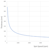
In general, the thickness of a spin coated film is proportional to the inverse of the square root of spin speed as in the below equation where ω is angular velocity/spin speed and hf is final film thickness.
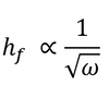
This means that a film that is spun at four times the speed will be half as thick. A spin curve can also be calculated from this equation such as shown below.

The exact thickness of a film will depend upon the material concentration and solvent evaporation rate (which in turn depends upon the solvent viscosity, vapor pressure, temperature and local humidity) and so for this reason spin thickness curves for new inks are most commonly determined empirically. Typically a test film is spin coated and the thickness measured either by ellipsometry or surface profilometry (Dektak). From this one or more data points, the spin thickness curve can be calculated - usually with a good degree of accuracy. The spin speed can then be adjusted to give the desired film thickness.
Emslie, Bonner, and Peck Model
Many researchers will use a simple proportionality rule (related to spin speed) to describe the final film thickness from spin coating, as expressed in Equation 1 (above).
However, this rule does not always apply and does not allow for predictions of film thickness without experimental data. There have also been several attempts to describe the process in a more rigorous manner. The earliest (and simplest) of these was by Emslie, Bonner, and Peck in 1958.1 This analysis made several approximations, including ignoring the effects of evaporation (the validity of which will depend on how volatile the solvent is) and ignoring the possibility of non-Newtonian behaviour. This means it is assumed that the viscosity of the fluid used will not be changed by stress. For a non-volatile, viscous fluid on an infinite rotating disk, Emslie’s model can be seen in Equation 2.

Where t is time since the start of the process, ω is angular velocity, r is the distance from the centre of rotation, ρ is the density, η is the viscosity and h is thickness of the fluid layer, (rather than the dry thin film). Here, ∂h/∂t represents the rate of change of thickness, and ∂h/∂r the rate of spreading.

If the film is considered initially uniform, this leads to a description of the fluid film thickness as seen in Equation 3.
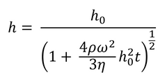
Here h0 represents the uniform thickness of the film at the start of the process (i.e. t=0). As this model does not account for evaporation, it cannot be used to calculate the exact thickness of the final dry film. An approximate dry thickness can be calculated from fluid film thickness by using the concentration of solute and solution density. To get an accurate value, including the impact of solvent viscosity and surface tension, a more detailed model is needed.
Meyerhofer Model
The first attempt to include evaporation effects was published by Meyerhofer in 1978,2 who modified the equations of Emslie, Bonner, and Peck (seen earlier in Equation 2) with the inclusion of a solvent evaporation rate:
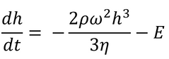
Here E is the uniform solvent evaporation rate, in units of solvent volume evaporated per unit area per unit time.
Meyerhofer proposed that early in the spin coating process, flow dominates the thinning process of the film (spin off); whereas later in the process (when the film is thinner and flow is slow), thinning is mainly due to evaporation. Meyerhofer also established that if the transition from fluid thinning to evaporation thinning is abrupt, then the film thickness can be estimated analytically – where it is assumed that the film is thin enough to ensure solvent concentration remains uniform through the depth of the film. This transition point will clearly be the point at which thinning by flow is equal to thinning by evaporation:
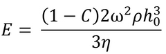
Where C is the volume fraction of solute in the film and h0 is the film thickness at the transition between the two film-thinning regimes.
This gives the final film thickness as:
Where C0 is the initial concentration of solute, and η0 equates to η(C0). The concentration of solute is assumed to remain at C0 until the transition of evaporation-driven thinning begins. Final spin coating film thickness can also be calculated without the solvent evaporation rate. This can be done by making several assumptions, including the assumption that air flow remains laminar during the process. This gives an overall equation as:

Where k is a constant specific to the coating solvent and for typical spin coating solvents k ≈ 1(-5)cm/s(-1/2). Readers will then recognize that this can be expressed as hf∝ ω(-1/2) which is equivalent to Equation 1, showing that the proportionality constant is a product of several other terms, including solution density, viscosity and concentration, and the properties of the solvent.
Despite what is shown in Equation 7, final film thickness from spin coating is not always proportional to ω(-1/2).This equation is dependent on numerous assumptions, and where these are not correct, the dependency will fail.
An example of this is when the transition between the two thinning regimes is not abrupt. This has occurred in some cases in research,3 where the spin coating process is terminated early. This means the cross-over to evaporative thinning doesn’t occur, and thickness and spin speed have a different relationship. If a longer spin time was used in these cases, it is possible that Equation 7 would have proven correct. Systems may also deviate from expected behaviour where non-Newtonian fluids do not cross over to a Newtonian flow before being immobilised by evaporative thinning. This mostly occurs in colloidal solutions or solutions close to the gelation point.
In many cases, it is most straightforward to establish the relationship for a given solution by using a ‘spin curve’. This can be done by spin coating a solution at varying spin speeds and then measuring the film thickness. In literature, there has also been success using semi-empirical models, as a combination of Meyerhofer’s equation and experimental data.4
Spin Speed
The range of spin speeds available is important as it defines the range of thicknesses that can be achieved from a given solution. In general, spin coating can produce uniform films relatively easily from about 1000 rpm upwards, but with care and attention good film quality can be achieved down to around 500 or 600 rpm in most cases (and even lower in some cases). Most common spin coaters will also reach a maximum speed of 6000 to 8000 rpm (although specialist coaters may go to 12000 rpm or higher). As such, a normal range of working spin coating rpm might span a factor of ten (from say 600 rpm to 6000 rpm) which in turn means a maximum variation in film thickness of around a factor √(10)=3.2.
For example, a solution which gives a film thickness of 10 nm at 6000 rpm will give a thickness of around 32 nm at 600 rpm and if a thicker film is required then the solution concentration would need to be adjusted. In the reverse scenario, if a solution gives a thickness of 100 nm at 600 rpm then the minimum thickness that can be achieved without diluting the solution will be 31.25 nm (100 / 3.2).
This dependence upon the square root of spin speed is both an advantage and a disadvantage. The disadvantage is that it means that the range of thicknesses that can be achieved from a given solution spans a relatively narrow range (around a factor of 3-4). On the other hand the advantage is that it allows precise control of film thickness within this range.
The maximum thickness that can be produced from a given material/solvent combination also depends upon the maximum concentration that the material can be dissolved in the solvent. For high solubility materials (100 mg/ml or higher), thicknesses of >1 μm can be achieved. Meanwhile for some low solubility conjugated polymers (a few mg/ml) the maximum thickness might be limited to 20 nm or so.
At low concentrations the thickness of a film is approximately linearly dependent upon the concentration of the material in the ink, however as concentrations increase this will affect the viscosity of the ink and thus a non-linear relationship will develop.
Spin Coating Duration
For most standard spin coating techniques the objective is to keep the substrate spinning until the film is fully dry. As such this will mainly depend upon the boiling point and vapor pressure of the solvent that is used but also on the ambient conditions (temperature and humidity) that the spin coating is performed in. For most solvents (such as the list below) a spin coating duration of 30 seconds is usually more than adequate and is therefore recommended as a starting point for most processes.
Table 1: Common solvents for which 30 seconds spin duration is usually adequate and those for which longer durations are required
| 30 seconds usually adequate | Longer spin speeds required |
|---|---|
| Water | Dichlorobenzene |
| IPA | Trichlorobenzene |
| Ethanol | Diiodooctane |
| Methanol | Octanedithiol |
| Acetone | Glycerol |
| Butanone | |
| Toluene | |
| Xylene | |
| Chloroform | |
| Chlorobenzene |
For higher boiling point (and/or lower vapor pressure) solvents, drying may take considerably longer (up to ten minutes in some cases) and therefore these solvents are most commonly used either as additives or with additional drying steps (covered in later sections).
Choosing a Spin Coating Method
In general, a dynamic dispense is preferred as it is a more controlled process that gives better substrate-to-substrate variation. This is because the solvent has less time to evaporate before the start of spinning and the ramp speed and dispense time is less critical (so long as the substrate has been allowed time to reach the desired rpm). A dynamic dispense also uses less ink in general although this does depend upon the wetting properties of the surface.
The disadvantage of a dynamic dispense is that it becomes increasingly difficult to get compete substrate coverage when using either low spin speeds below 1000 rpm or very viscous solutions. This is because there is insufficient centrifugal force to pull the liquid across the surface, and the lower rotation speed also means that there is increased chance that the ink will be dispensed before the substrate has completed a full rotation (at 600 rpm the substrate is rotating once every 0.1 seconds, commensurate with a fast pipette drop). As such, Ossila generally recommend using a static dispense at 500 rpm or below and with either technique a possibility in the region between 500 - 1000 rpm.
Dynamic Dispense Spin Coating Technique
For the majority of spin coating above 1000 rpm, a dynamic dispense should be used as standard unless there are any special circumstances or difficulties.
A pipettor is normally used to dispense a known amount of solution each time - usually 20 µl for most common substrates/inks on standard sized (20 x 15 mm) substrates or around 100 µl for 50 x 50 mm substrates. However, if there is a problem with wetting then increasing the volume may help.
In this example we demonstrate using AI 4083, a PEDOT:PSS formulation typically used as a hole transporting layer but the technique is commonly used with a large variety of inks and photoresists.
Here the substrate is spun to 6000rpm and the solution (a quantity of 30-40μl) is dynamically deposited (i.e. during the spinning process) but the process works well for spin coating speeds of around 500 RPM and upwards.
In order to get a high quality and consistent thin film the below points must be observed:
- The substrate should have reached it's desired rotational speed before the dispense happens (usually only a few seconds).
- The ink should be deposited as close to the centre of the substrate as possible otherwise you may end up with a gap in the middle.
- The ink should be deposited in one quick and smooth action.
- The ink should be deposited in one and only one drop in order to prevent multiple coats.
- There should not be any bubbles blown onto the surface from the pipette.
- The pipette tip should never touch the rotating substrate.
It's also worth noting that for spin coating, best results can be achieved when using a pipettor in a non-standard way. Normally when pipetting a solution the pipette would be used to the second stop so that additional solution is sucked up into the tip and then discarded afterwards. However, this leads to a higher chance of additional drops or bubbles being cast onto the surface. As such, it is advisable to only use pipettors to the first stop when spin coating.
The above points will help to provide the best possible film uniformity for a particular substrate. In a research environment, however, new users in particular (but also for experienced users) often find that the variation between substrates is usually greater than the variation across a substrate. While often this is a small effect it can be an important consideration - especially for statistical results.

As such, to get the best possible consistency between substrates there is a critical "practice factor". This refers to the fact that once an action (or combination of actions) has been done many times it is committed to "muscle memory" which means that it is done automatically with little or no conscious effort. This generally means that the dispense happens more consistently and precisely which has a knock on effect for the film quality.
Static Dispense Spin Coating Technique
As spin speeds decrease below 1000 rpm or with very viscous solutions it becomes increasingly difficult to get a high quality film. Therefore, if possible, it is generally recommended that the ink is reformulated (increased concentration or change in solvent) to allow spin coating above this speed. However, there are many situations in nanotechnology where this is either not desirable or not possible. For example, better crystallization will happen at low speeds and some materials just do not have sufficient solubility to reach the desired thickness at 1000 rpm.
A dynamic dispense can be achieved at speeds all the way down to around 500 rpm, however it becomes more difficult to get complete substrate coverage and so more ink is required (using a 50 µl dispense rather than 20 µl will help with coverage but at the expense of greater material wastage). As such, the cut-off point can be considered to be around 700 rpm, below which the static dispense spin coating method starts to give better film quality.
When using a static dispense it is usual to coat the entire substrate (or at least all of the active part of the substrate) before starting the spin coating. However, this in itself can cause several issues. The first is that unless the substrate surface gives particularly good wetting for the ink (i.e. the ink likes to spread out across the surface) then it is usually necessary to use the pipette tip to "pull" the ink across the surface. However, it is of course especially important for the pipette tip to never touch the surface of the substrate in the active areas as this can change the surface properties and/or damage any other layers present.
By carefully placing the pipette tip close to the surface such that it touches the edge of the ink droplet, it is possible to move the ink around the surface without touching it. Alternatively, if the edges of the substrate are not critical then the pipette tip can be moved around the edge of the substrate to pull the meniscus around. A third alternative is just to add more and more ink until the substrate is fully covered - however this is in general not recommended as it may take up to a ml of solution in extreme cases for this to happen. The below videos show all three of these techniques being used for static dispense spin coating.
Finally, in some cases it is desirable to statically dispense a viscous solution and ensure that it coats right to the very edge of the substrate (for example spin coating PMMA as a gate insulator for prefabricated ITO OFET substrates). In this case it is not easy to use the pipette tip to pull the meniscus to the edge without touching it due to the viscosity of the ink and the relatively low wettability.
Instead, use a different spin coating method where the pipette tip is angled at 45 degrees to the substrate and moved along the far edge of the substrate. This creates an effective technique to coat the PMMA right to the very edge of the substrate without touching it.
However, one of the main issues for a static dispense is that the solvent in the ink has some time to evaporate before the spin coating process begins. For low vapor pressure solvents such as water this is not too much of an issue, however for high vapor pressure solvents such as chloroform (around 10x higher than water) it can be critical and the time between depositing the solution and the start of spinning can make a big difference to both film thickness and film quality. This is the primary reason why a static dispense gives lower substrate-to-substrate film uniformity and why a dynamic dispense is recommended if possible.
Practical Spin Coating Tips
Special Requirements for Spin Coating Nanoparticles
In many areas of organic electronics and nanotechnology, the casting and drying stages of an ink are an integral part of the technology, and is where all the "action" happens. It is sometimes referred to as "the science of paint drying" and in all of the examples below, part or all of the key process happens during the drying of the ink:
- π-π stacking/crystallization of a small molecule or polymers
- self-assembly of a block-copolymer
- phase separation of a polymer-fullerene blend
- aggregation/assembly of nanoparticles and colloids
Control of this process is critical. In practice, this means that when spin coating nanoparticles for OE/nano applications, the properties of the film don't just depend upon its physical characteristics (thickness, uniformity) but also very strongly upon the processing (drying time and conditions). By comparison, in many more general spin coating processes, such as applying a photoresist, the end result is broadly independent of the exact application route. For this reason, variations on the usual technique are often used in organic electronics and nanotech - especially in a research environment.
In particular, for industrial processes spin coating would generally only be recommended at speeds of >1000 rpm to ensure the best uniformity. However, in OE/nanotech, spin speeds down to 200 rpm might be used to slow down the drying process and allow additional time for self assembly. An industrial process engineer might not consider this to be spin coating at all but this sort of "pseudo-spinning" can be a powerful tool to investigate order and self assembly.
The figure below shows how drop casting slowly without rotation can be a good way to provide highly ordered films at the nanoscale at the expense of uniformity across the substrate.

By spin coating at very low speeds it is possible to get a combination of the high levels of nanoscale order produced by drop casting with the uniformity of spin coating.
Other issues in research environments are the requirement to coat often very small substrates, the desire to use in difficult spaces such as laboratory glove boxes, and the wish to keep services (vacuum, compressed air or nitrogen) to a minimum. The ability to cope with chlorinated or aggressive solvents while being low-maintenance is also of beneficial for many applications. As such, this guide details a full range of spin coating techniques and issues that might be encountered in a typical research lab.
For most applications the most important consideration is the thickness of the film that is produced during spin coating.
Probably the most important aspect to consider is the spin coating method used to dispense the solution - either a static dispense or a dynamic dispense.
In a static dispense the solution is placed upon the substrate while it is stationary and usually the entire substrate is covered in the solution before rotation begins. The spin coater is then started and brought up to the required speed as fast as possible.
In a dynamic dispense, the substrate is first started spinning and allowed to reach the desired spin speed before the solution is dispensed onto the centre of the substrate. The centrifugal force then rapidly pulls the solution from the middle of the substrate across the entire area before it dries.
Normally a pipette or pipettor of some description is used to dispense a known volume of liquid on the surface.
Spin Coating Small Substrates and Wafer Fragments
This video demonstrates the spin coating of small and odd-shaped substrates (in this case silicon wafer fragments) that in many cases would be too small to coat using a standard spin coater due to the size of the vacuum chuck (and so would otherwise need mounting).
The spin coater chucks can be custom designed to hold arbitrary shaped substrates and work well with under-sized wafer fragments. The only general requirement that in order to get good coverage when dynamically dispensing a solution the fragment should cover the centre of the chuck so that centrifugal forces will spread it over the entire fragment. However, when using a static dispense this doesn't matter.
You can download the design to make your own chucks for the Ossila spin coater and even 3D print them if you wish. We can also design and make them for you.
Automated Dispensing
For certain situations manual dispensing of solutions during spin coating may not be appropriate, these include:
- Specific timing needed for the dispensing of solutions.
- Specific dispense rate of the solution during spin coating.
- Dispensing of multiple layers being too repetitive and time consuming.
- Time between multiple dispenses is too short to perform manually.
In these situations the dispensing of the solution needs to be automated, this can be done through the use of a programmable syringe pump. Syringe pumps work by displacing a volume of liquid at a specified rate at a given time, these values can be controlled to extremely high degrees of accuracies. Rates of dispense can vary from as low as 0.1 nl/s to as high as 10 ml/s, while the timing of the dispense can be controlled to within 10 ms allowing for a level of control that is not possible with manual solution dispensing.
Syringe pumps are especially effective when dealing with dispensing multiple solutions, some examples of situations where multiple solutions are required are:
- Multi-layered structures that require alternating multilayer coatings, such as distributed agg reflectors (D's), can be fabricated rapidly and reproducibly when using an automated dispenser.
- In situations that require the washing of the substrate with a solvent before the dispensing of the solution to improve the wetting on the substrate, timing the dispensing of the solution so that it occurs just as the solvent is evaporating can dramatically improve the wetting.
- When surface washing. The washing of the top surface of a deposited layer where the surface of a dry or a semi-dry film can be washed with a solvent in order to alter the properties of the upper surface and improve morphological structure. This can be done when depositing PEDOT:PSS, the post deposition washing with solvents such as methanol or DMSO can significantly improve the conductivity of the film.
- For quenching of deposited films. Quenching of films is done by flooding the drying film with an anti-solvent causing the material in solution to rapidly precipitate. Syringe pumps excel in these situations as you can not only time when the quenching occurs but also the rate at which it happens something that is impossible to do accurately during manual deposition.
Ultra-low Spin Speeds and Covered Drying
As mentioned above, spin coating below around 1000 rpm, the uniformity of films begins to be affected and below about 500 rpm this can cause significant issues. However, it is still possible to process films at speeds even lower than this and still get good results - albeit at the expense of consistency.
In some cases it may even be possible to spin films at speeds as low as 120 rpm. While this can not really be described as spin coating it does still provide a significant increase in uniformity over drop casting because there is still some centripetal force. It also ensures that there are no effects due to the substrates being on a slight slope (getting a substrate sufficiently flat that an ink droplet does not move and dries evenly over the course of 5-10 minutes is difficult without a goniometer).

However, when spinning at ultra low speeds it's also important to consider the edge bead removal which is described below.
As described in previous sections, a slow drying film is often desirable to allow for self organization to occur, but reducing the spin speed often results in non-uniform films. On the other hand the solvent is changed to something with a high boiling point, the end result is often a thinner film (the ink has more time to migrate to the edge of the substrate before drying) with poor surface wetting (higher boiling point generally means higher intermolecular interactions and therefore more surface tension).
Spin Coating with Solvent Blends
A good way to optimize spin coating uniformity is to mix two solvents together; using a major component of something that evaporates relatively quickly and a minor component of something that is relatively slow to evaporate. By using this combination it is often possible to get the best of both worlds; during the spin coating process the major component evaporates quickly to give good coverage and a uniform thick film, and the remaining minor component still leaves enough plasticity for the molecules to self-organize before the film is completely dry.
| Solvent A | Solvent B | Mixture of A + B |
|---|---|---|
 |
 |
 |
Example of solvent blends.
- Solvent A: If a low boiling point solvent (high evaporation rate) is used then coating can be achieved more easily but an amorphous (disorganized) film is produced.
- Solvent B: If a high boiling point (slow evaporation rate) solvent is used then coating is harder because the ink has time to dewet and is flung off the edge of the substrate leaving no coating.
- Mixture of A & B: If a mixture of solvents is used with a majority of low boiling point (fast evaporation rate) with minority of high boiling point (slow evaporation rate) then coating can still be achieved because the fast evaporating solvent is removed quickly leaving a plasticised film that is less likely to dewet but also gives the molecules time to organize themselves.
An example of this which works to good effect is the spin coating of P3HT for OFETs. Spin coating from pure chlorobenzene will give worse performance than spin coating from trichlorobenzene. However, spin coating from trichlorobenzene gives poor wetting and a very rough surface. By spin coating from a solution of 98% chlorobenzene and 2% trichlorobenzene the wetting is significantly improved and the performance remains almost as good.
Visible Assessment of Drying and Film Uniformity
Learn to trust your eyes - they are the primary tool and first line of analysis for almost all device engineering.
Microscopy by optical, electron, AFM or STM techniques will obviously give you a better and more quantitative assessment of nanostructure. Dektak or ellipsometry can provide better thickness and roughness calculations. However all of these techniques are slow, may damage the sample and/or introduce additional delays or variables to a process that can be critically dependent upon timings. They are not suitable for assessing every pixel on every substrate at every stage of a process - at least in an R&D environment.
The eyes are a highly sensitive and very versatile optical recognition system capable of discerning small differences quickly and effectively. With training and the correct lighting you can quite easily spot a 5 nm variation in film thickness just by looking at the color. As such, inspecting a substrate visually before and after each step is critical for understanding and improving variation and performance:
- Does the film look uniform?
- Is the color (thickness) as it should be?
- Does the surface have a glass-like, smooth-matt or rough-matt finish?
- Are there any aggregates on the surface?
- Are there any pin-holes or comet streaks?
In addition, with the correct lighting it is also possible to assess whether a spin coated layer is dry while the substrate is still spinning. In some cases (such as for many conjugated polymers) this is relatively easy because the film changes color as it dries. In other cases it will be more difficult as there is no obvious color change.
However, as a film dries it generally reduces in thickness from a wet layer of a few tens-hundreds of microns to a dry layer of a few tens-hundreds of nanometres. During this time the film thickness is of the order of a few wavelengths of visible light which means that the reflectance properties will be interference based and highly non-linear. As such, even for a nominally transparent material in a transparent solvent the apparent color will change as the film decreases in thickness and once the film stops changing color it is predominantly dry (note that residual solvent is another issue and can be very hard to remove).
Ambient Conditions and Changes in Drying Time
For many organic electronics and nanotech applications the drying time and film properties are intimately linked and for this reason the ambient conditions can sometimes have significant effects. A professional cleanroom will usually have a relatively well controlled temperature and humidity and a glove box is usually a pure nitrogen atmosphere. However, research labs are often not so well controlled and while this may not make much of a difference in most cases there are some extreme examples that can affect consistency and result in spin coating defects.
Here in the UK the ambient humidity in summer can swing quite dramatically from less than 20% to nearly 100% depending upon the weather. On times of very high humidity, typically during a rainstorm, films spun from aqueous solutions may still be wet after the normal 30 second spin duration and this can have a significant effect on device performance. As such, although the majority of work is done in temperature/humidity controlled environments it is advisable to keep a close eye on the ambient conditions and place a thermometer/hygrometer next to the spin coater.
If coating multiple large substrates with large volumes of solvent (100 µl or more) then it is also possible for the solvent to start pooling in the basin of the spin coater, which can also have the same effect as to increase the ambient vapor pressure and increase drying times. A simple solution to this is to wipe dry the spin coater basin after every spin if large volumes of solvent are used.
Spin Cleaning and Wash Steps
Spin coating can also be used to clean substrates, however experience of this is that in general it produces relatively poor results compared to sonic bath based cleaning and is slow compared to cleaning a batch of substrates at a time. It also often results in large volumes of solvents being used in the spin coater, which can be a problem if these steps are performed in an environment where that solvent needs to be removed (for example a laminar flow).
However, there are times when spin cleaning and wash steps can be very useful, for example HMDS and certain other surface modification treatments benefit from a spin-wash. Meanwhile, spin coating a semi-orthogonal solvent can also be used to remove certain additives.
When spin washing, researchers generally use a dynamic dispense of a medium volume of solvent (50 µl for the standard 20 x 15 mm substrates) and may wash several times. Beware of the fact though that this will create significant solvent vapor that can affect the drying dynamics of subsequent films if the solvent is not removed first (usually by wiping excess solvent from the inside of the spin coater with a clean-room tissue).
Preventing Common Defects
Two Step Spin Coating and Edge / Corner Bead Removal
When spin coating with viscous or high boiling point solvents such as trichlorobenzene at very low spin speeds (below 500 rpm), the middle of the substrate often dries significantly quicker than the edge of the substrate. While the middle might be dry within a few seconds, in some cases the edge of the substrate may take minutes to dry. While the edges of the substrate are often designed not to contain any active/critical components, if the spin coater stops then the edge/corner bead may spread back towards the middle which can ruin the film quality.
There are essentially two ways to remove the edge/corner beads. The first and more preferable way is to use a two-step spin, with the first step programmed to give the desired film thickness and sufficient time for the ink to dry over the majority of the substrate, and a second step at maximum rpm to fling off the corner beads and dry the remainder of the substrate.
In most cases a two stage spin is the easier and preferable way to remove edge beads to improve spin coating uniformity. However there are some occasions where the second stage (high speed) spin is not desirable, for example if you want to remove the substrate from the spin coater while it is still slightly wet for further processing such as a methanol wash, vacuum dry or even slower drying in a solvent saturated atmosphere. In these cases a second but more delicate technique can be used to remove edge beads where by a fine cotton bud is used to absorb the excess solution while it is still spinning.
The key is to avoid knocking the substrate off the chuck and also not to damage the active area on the substrate. For effective corner bead removal via cotton bud follow the below points:
- Approach the substrate very slowly.
- Steady your hand by resting it on the lid and use the centre-hole in the lid to steady and guide the cotton bud in.
- Try not to touch the actual substrate; hold the tip of the cotton bud a fraction above the substrate so that it is in contact with only the edge bead but not the substrate.
- Pay attention to the movement of the cotton bud; even the most gentle touch of the cotton bud onto the substrate will produce a vibration which you should be able to feel.
- Watch the cotton bud closely; many organic and nanotech inks are colored so you should be able to see when the cotton bud is close enough to absorb the ink.
- Try to keep the cotton bud as close to the edge of the substrate as possible.
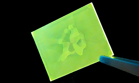
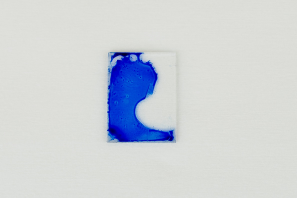
Avoiding a Hole in Middle of Film
A common spin coating defect for beginners is to see a hole in the middle of the substrate with no coating on it such as in the image below.
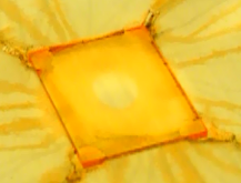
This is typically caused by the ink not being dispensed in the middle of the substrate. Since the centrifugal force will always make the ink flow to the edge of the substrate the middle will not get coated. By dispensing the ink closer to the centre of the substrate this should be eliminated. Note that by using the edge of the centre-hole in the lid to guide the pipette it can be positioned more accurately.
Avoiding Vacuum Warping of Substrate
Many spin coaters use vacuums to hold the substrates in place. Not only does this often cause problems for spin coater maintenance (the vacuum is often trying to suck in the ink and solvents) but it can also warp the substrates slightly which causes uniformity problems. The extent of the problem will depend upon the thickness of the substrate, the strength of the vacuum and the size of the vacuum aperture. The image below demonstrates the effects of vacuum warpage on film uniformity.
The mechanical stiffness of a substrate is proportional to the cube of its thickness so a 1.1 mm thick substrate will be eight times stiffer than the equivalent 0.55 mm substrate. In general, substrate warping becomes an issue for substrates of less than around 1 mm in thickness and the effects are worse at low speed (where there is less centripetal force).
The effects of vacuum warpage are one of the primary reasons why Ossila developed the vacuum free spin coater. Firstly, in order to improve the uniformity of the films, the vacuum had to be eliminated. This led to the design of specialist chucks to place on top of older spin coaters to hold the substrates in place mechanically. This technique worked initially, but the subsequent design of a new spin coater eliminated the demanding servicing requirements that come with having a vacuum pump.
Although we have worked with flexible PET substrates extensively in the past to make real devices such as OLEDs and OPVs, here we take the the technique to the extreme and demonstrate spin coating parafilm (yes, really, parafilm). Even we didn't think this would be possible until we tried it but it's a great demonstration that spin coating onto flexible substrates is really easy using a vacuum free chuck.
The below points will also help to alleviate the problem of vacuum warpage:
- Use thicker substrates
- Use higher spin speeds
- Mount the substrate on a thick carrier plate before spin coating
Spin Coating Low Viscosity Solvents
When spin coating viscosity of a solvent can have a major impact on film quality. Certain solvents which are prevalent in research fields for historical or other reasons have very low viscosities which can provide significant issues. Examples of this kind of solvent include chloroform and acetone and there are two primary issues here:
- The solution dripping out of the pipette before it is supposed to
- The film drying before an even wet-layer has been produced, which creates swirls in the substrate
With regards to the ink dropping out of the pipette before it is supposed to, the first thing to do is to use the smallest size pipette tip that is available as it will have a smaller diameter aperture at the end and reduce dripping. It also helps to pipette the minimum amount of ink required for coating as that will reduce the effect of the weight compared to the surface tension (10 µl of solution will weigh half as much as 20 µl but the surface tension remains the same).
If the solvent is halogenated (such as chloroform) then it can also help to leave the pipette tip in the ink for a few seconds before removing it. The reason for this is that most pipette tips are made of polypropylene which will not dissolve in halogenated solvents but will swell slightly which will reduce the effective diameter of the aperture.
This technique does not work for non-halogenated solvents such as acetone as they will not swell the polypropylene. As such an alternative is to tilt the pipettor at an angle to reduce the weight to surface tension ratio, returning the pipettor to vertical only just before dispensing the solvent. Care must be taken not to tilt the pipettor to the extent that solvent will enter the pipettor and damage it.
Incomplete Coating of Substrate
The wetting of an ink onto a substrate is generally characterized by the contact angle of the liquid onto the surface. A low contact angle means good wettability (the ink likes to spread across the substrate) while a high contact angle means poor wettability (the ink likes to ball up).

The contact angle will depend upon the surface tension of the liquid and the surface energy of the substrate. A liquid with a high surface tension wants to ball up more than a liquid with a low surface tension. Meanwhile, a substrate with a high surface energy is more likely to attract the ink as it will result in an overall lower energy state.
Some ink / substrate combinations will coat very nicely with the ink wanting to spread across the surface while in other cases it will want to ball up. In extreme cases this can mean that it is simply not possible to coat an ink onto a surface. More commonly it is simply difficult to wet a surface and this often results in partial coating of the substrate.
The first and simplest solution to this problem is simply to deposit more ink - for example for with standard 20 x 15 mm substrates you might increase the dispense volume on the pipettor from 20 to 50 or even 100 µl. Increasing the temperature of the ink and dispensing warm or hot can also help by reducing the surface tension and increase the evaporation rate so that there is less time for the ink to dewet from the surface.
However, if the above options don't work then it is usually necessary to either change the solvent in the ink to something with a lower surface tension or to treat the substrate in some way such as by a UV/ozone or oxygen plasma to increase surface energy (note that this is often not desirable for organic based transistors where a low surface energy is key to high performance).
Pin Hole Defects & Comet Streaks
The physical and chemical cleanliness of a substrate is critical for high quality films regardless of the application method. For spin coating the effect of dust and particulate matter is usually to cause pin holes and comet streaks, however this can also be caused by particles in the ink described in the below section.
To remove dust and particulate matter the use of an electronic grade detergent such as Hellmanex III is generally recommended. However, it's also important to remove any residues on the surface for which a semi-polar solvent such as acetone/IPA is helpful. Finally, it is usually worth chemically preparing a substrate before applying the first layer by using either a basic NaOH solution or an oxygen plasma/UV Ozone to produce "-OH" terminations which are excellent for most coating processes. As such, the below standard cleaning routine should be used for most substrates. Where possible, use a solution-based NaOH process for providing "-OH" surface terminations for ease and simplicity but in the case of silicon this will wreck the surface, so use an oxygen plasma treatment instead.
Once a substrate is clean, store it in a clean environment (often in DI water) to avoid dust and other contaminants. This is important as even though dust can be blown off a substrate it often leads to a change in surface energy where the dust particle was placed which can lead to pin-holes on the surface such as the below example.

Aggregation and Filtration
For many OE/nanotech inks there is the possibility of aggregates or crystallites forming in solution prior to deposition of even during the spin coating process. This can lead to comet streaks or large lumps of aggregation left on the surface.
Generally, heating and stirring a solution will help to dissolve the active materials and then cooling and filtering will remove any aggregates and undissolved material and this can often have significant effects on device performance. In the below examples, improvement can be seen in device performance for both OFETs and OPVs after a solution has been filtered.

However, for many materials an ink solution may not be stable and will re-form aggregates or crystallites over time, such as the below examples of P3HT films, PCBM crystallites and F8BT aggregates, all of which will form if an ink is left standing for long times (hours to days).
| PCBM crystallites under an optical microscope | P3HT aggregates in a thin film via AFM | F8BT aggregation in a working OLED pixel |
|---|---|---|
 |
 |
|
| Several weeks storage prior to spin coating | 90 minutes cooling prior to spin coating | Aggregation during spin coating at low speed - filtered immediately prior to spinning |
Aggregates of different materials and the approximate timescales required. In all cases the solutions were filtered prior to storage.
In some cases it's possible to re-dissolve these particles by re-heating/stirring and often it's worth filtering a second time after the solution has cooled. However, in some cases, such as for PCBM, the energy of crystallization is significant and therefore it's very difficult, if not impossible (depending on the solvent) to re-dissolve them, therefore fresh solutions should be used each time.
However, before filtering any solution it is always worth considering the size of any solutes relative to the filter pore size; while polymers, PCBM, and small nanoparticles (<20 nm or so) can all be filtered without problems, larger nanoparticles or graphene flakes have a large chance of being caught in the filter and totally removed from the solution (leaving just solvent).
Coating Difficult Solutions
While the spin coating process is very simple, it is not always easy to produce a perfect film. Many spin coating problems can result from the properties of the solution being used, rather than from problems with the spin coating technique itself. Poor film uniformity can result from poor solution solubility, highly-volatile solutions, poorly-wetting solutions, and viscous or non-Newtonian solutions.
This section discusses why these types of solutions can cause issues, what these issues are, and what techniques can be used in order to improve the quality of the film.
Solutions With Poor Solubility
Many researchers will have faced issues coating films where the solute has poor or marginal solubility in the solvent used. This is especially common when using high molecular weight materials, or when trying to replace the solvent in an established system. Solutions with poor solubility can produce films with unwanted precipitation, especially as solvent evaporation drives the concentration above the solubility limit, leading to comets or particulates in the final film. Precipitation can be avoided by keeping solutions below the solubility limit of the material, but this may lead to deposited films being too thin.

Insufficiently-thick films are best tackled with low spin speeds. As such, they may be more suited to static deposition, because dynamic deposition at low speeds can result in incomplete surface coverage. Solubility itself can be improved through additional components, such as by generating a solvent blend or using a solvent additive - where the main component gives the best performance, and the additive improves solubility. Mixing solvents can be informed by using Hansen solubility parameters to match the solvent and solute, and produce as ideal a solubility as possible.5
Solubility can also be improved through hot casting, where the solution is heated up and cast whilst at an elevated temperature. For most solutions, solubility increases as a function of temperature. Therefore, heating can be an effective way of increasing the solubility limit of the material. This is common whilst using some polymers with a tendency to aggregate at room temperature,6 such as PffBT4T-2OD (PCE11).
Another method used to help improve film quality is the sonication of solutions with poor solubility. Although sonication itself does not increase the solubility limit of materials, it can improve the rate of dissolution, which can be a slow process for materials like high molecular weight polymers. In some cases, filtering a solution will improve film quality. However, this is not always recommended, as important solution components can sometimes be accidentally filtered out.
Solutions with Extreme Volatility
Solutions with either very high or very low volatility can cause issues in spin coating.
When highly-volatile solutions are used, they can easily drip out of pipettes during spin coating, thus requiring an adjustment of technique. This is due to the evaporation of solvent inside the pipette, which consequently increases the pressure within the tip. This is a problem as the solution will not be deposited in one continuous motion - resulting in uneven coating. The resulting issue can appear as swirls, where each droplet only partially covers an area of the substrate. For the most volatile solvents - typically those with boiling points below 50°C - swirls can be seen even when using a continuous dispense technique. To counter this, either a static dispense technique or a larger volume of solution should be used.
Other evaporation defects that can occur are due to Marangoni instabilities, where a secondary flow is introduced in the wet film due to surface-tension gradients. This is a consequence of convection currents within the solution, caused by a temperature or concentration gradient. Temperature gradients will occur due to evaporative cooling, and concentration gradients will occur when evaporation is faster than diffusion through the film - meaning that the more volatile a solution is, both are more likely to occur. Marangoni defects normally manifest as a flower-like pattern, with a dense set of cell-like defects in the centre. Further from the middle, these ‘cells’ become stretched out - forming striations, or wavy films.
By slowing the rate of evaporation - and subsequently decreasing the temperature and concentration gradients in the film, this defect can be overcome. One such way of decreasing the evaporation rate is to use a less volatile solvent as the main solution. If this is not possible, even small amounts of a lower-volatility solution will slow down the evaporation process - usually without having a significant impact on solubility or performance. This can also be achieved by slowing down the rotation or acceleration to prolong the spinning time, therefore allowing viscous flow to stabilize the film. In some cases, very slow spin times can lead to non-uniform films. In these scenarios, it is best to move to static dispense spin coating.
Finally, saturating the spin coating atmosphere with the main solvent will also slow the rate of solvent evaporation. However, this may not be practical due to the amount of solvent waste, as well as the potential health and safety issues involved.
Marangoni defects are not always seen when using high-volatility solutions. This is because where the solution also has particularly low or high viscosity, viscous forces dominate over the Marangoni flow. However, even if uniform films have been formed, fast evaporation can lead to unfavorably amorphous films. Thus, slowing the rate of evaporation is still important to yield better crystallinity.
Solutions with low volatility can also cause issues, mainly through long drying times. Using very long spin times to dry the solvent can lead to very thin films, as evaporation takes place so slowly - which means that more of the fluid is removed via flow thinning. To tackle this without impacting film thickness, a slower drying step can be introduced as a second stage - typically at a spin speed of approximately a quarter of the main speed. Low-volatility solvents can also cause more pronounced edge effects. This is because it takes a longer time for the solution to be thrown off from the edge of the substrate, therefore slow solvent evaporation leads to a thicker film around the edges compared to the centre.
Low volatility solutions may also have poorer wetting due to higher surface tension. In the case of very viscous solutions, a static dispense may be required.
Poorly-Wetting Solutions
In some cases, solutions may be perfectly dissolved and of ideal volatility, but will still produce films with poor uniformity due to incomplete wetting. This issue often manifests as incomplete coverage of the substrate and can sometimes be improved by simply depositing more ink, or by improving fluid flow through an initial ‘spreading step’. This 'spreading step' is often short and at a slow speed, and works by spreading the solution across the substrate before the main high-speed step immobilises it. This is similar to the method used to spread photoresists.
If poor wetting is due to a rough or uneven substrate, this can be improved by planarising the surface, as sometimes used in organic thin-film transistors.7 Here, an inert (and often thick) layer provides a smoother surface - potentially with more favorable surface energy - for better solution wetting.
Most poor wetting can be improved by increasing the surface energy of the substrate through treatment such as UV Ozone Cleaning or argon plasma. Alternatively, the surface tension of the solution can be modified via the use of a surfactant. These generally will decrease the surface tension at the solution-air interface, improving wetting on the substrate.
Viscous and Non-Newtonian Solutions
Highly-viscous solutions can also present challenges, as they will be more resistant to deformation from shear forces during the spin coating process. This means that the outflow of solution from the substrate (as it reaches the desired spin speed) will be slower, and thinning of the solution during spinning will be reduced. This can lead to incomplete spreading of the solution across the surface of the substrate, which can sometimes be counteracted by static spin coating with a large amount of solution. Reduced thinning may also lead to undesirably thick films, thus requiring the use of lower solution concentrations.
For some solutions (e.g. colloidal solutions, polymer solutions, or solutions close to gelation), their behaviour will be significantly non-Newtonian. Newtonian solutions have a viscosity that does not change with force applied, meaning that shear stress and shear rate will scale linearly. In contrast, non-Newtonian solutions can change viscosity depending on the force applied, meaning shear rate responds to shear stress in a different way. These are known as 'shear-thinning' or 'shear-thickening' solutions, depending on whether or not the force applied decreases or increases the viscosity. Some solutions may also exhibit thixotropic or rheopectic behaviour, where the viscosity depends both on i) force applied, and ii) on how long it is applied for.
For these types of materials, final film thickness will not always be proportional to the inverse square of the spin speed - so film thickness can be difficult to predict, and final films are not always level. Due to their diverse range of behaviours, non-Newtonian solutions can present a significant challenge when it comes to the deposition of highly-uniform films.
Spin Coater

Keep Reading...
 Spin Coater Speed: Key Features
The spin speed features in your spin coater are important as they can characterize and alter the thin films you produce.
Read more... How to use the Dynamic Dispense Spin Coating Method
Video guide for the dynamic dispense spin coating method.
Read more...For more information and details on film thickness equations and mathematical models, see:
- Journal Article: Dynamic, crystallization and structures in colloid spin coating, M. Pichumani et al., Soft Matter (9), 3220-3229 (2013); 10.1039/C3SM27455A.
- Book: Liquid Film Coating. R. G. Larson and T. J. Rehg, ed. S. F. Kitsler and P. M. Schweizer, Chapman & Hall, 1st edn, 1997, ch. 14, pp. 709-734.
For further information on spin coating difficult solutions, see:
- Hansen Solubility Parameters: Organic photovoltaic devices with enhanced efficiency processed from non-halogenated binary solvent blends, J. Griffin et al., Org. Electron. (21), 216-222 (2015).
- Marangoni Instabilities: Liquid Film Coating. R. G. Larson and T. J. Rehg, ed. S. F. Kitsler and P. M. Schweizer, Chapman & Hall, 1st edn, 1997, ch. 14, pp. 709-734.
References
- Flow of a Viscous Liquid on a Rotating Disk, E. G. Alfred et al., J. Appl. Phys. (29), 858–862 (1958).
- Characteristics of resist films produced by spinning, D. Meyerhofer, J. Appl. Phys. (49), 3993–3997 (1978).
- An Investigation of the Thickness Variation of Spun-on Thin Films Commonly Associated wtih the Semiconductor Industry, J. W. Daughton, J. Electrochem. Soc. (129), 173–179 (1982).
Contributing Authors
Written by
Product Developer
PhD Student Collaborator
Product Developer