Troubleshooting Cyclic Voltammetry and Voltammograms

Cyclic voltammetry is a powerful and versatile electrochemical technique. With modern potentiostats and software packages, the method is relatively straight-forward to perform:
- Create a solution consisting of the compound of interest, an electrolyte, and a solvent which dissolves both
- Add the electrolyte solution into the electrochemical cell
- Place the lid on the cell and insert the working electrode, counter electrode, and reference electrodes
- Connect the cell to the potentiostat
- Start the electrochemistry software and enter the desired experimental settings
- Click the ‘Measure’ button (or equivalent).
Despite this apparent simplicity, things can still go wrong, leading to incorrect and distorted cyclic voltammograms.
Problems with cyclic voltammetry are often caused by relatively small mistakes, but when faced with an unknown issue, it can be difficult to determine the source. In these instances, there are several different approaches that can be taken to troubleshoot the issue, depending on the nature of the problem.
For problems originating from the equipment being used, a general troubleshooting procedure (described below) can be used to narrow down and identify the issue. If you are using an Ossila Potentiostat, the supplied Test Cell Chip can be used in place of an electrochemical cell to provide controlled conditions for four different test scans. Alternatively, if you are familiar with some of the common things that can go wrong, you may be able to diagnose the issue through observation.
Once the cause of the issue is known, it can often be fixed with relative ease.
Contents
- General troubleshooting procedure
- Common problems
- The potentiostat is producing voltage compliance errors
- The potentiostat is producing current compliance errors
- The voltammogram looks unusual or different on repeated cycles
- A small, noisy, but otherwise unchanging current is being detected
- The baseline is not flat
- There is a large reproducible hysteresis in the baseline on forward and backward scans
- The cyclic voltammogram has an unexpected peak
- A peak appears on the voltammogram over time
- The voltammogram peak appears distorted
- The difference between the HOMO and the LUMO differs to other measures
- References and appendix
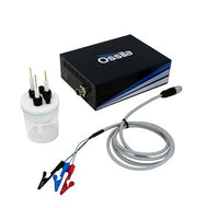
Potentiostat

- Perfect for Cyclic Voltammetry
- Intuitive Software
- Affordable
Available From £1700
General Troubleshooting Procedure
A general troubleshooting procedure for cyclic voltammetry has been proposed by A. J. Bard, and L. R. Faulkner [1] to help identify problems with the potentiostat, cables, or electrodes. This procedure assumes that the electrochemical cell has been set up correctly (i.e., that all chemicals are present in the correct quantities, and the desired voltammogram falls within the voltammetric window of the system).
Problems of this type typically result in unusual looking cyclic voltammograms, so it is helpful to start by thinking about how a normal voltammogram should look.
The simplest possible cyclic voltammogram shows a one-electron reduction observed via cyclic voltammetry at a scan rate of 0.1 V s-1. A standard voltammogram obtained under these conditions is expected to have a peak current of (200 μA cm-2 mM-1) ac [1], where a is the area of the electrode in cm2, and c the concentration of analyte in mM. Note that this value changes for ultramicroelectrodes and is reported to be (0.2 nA μm-1 mM-1) rc, where r is the radius of the electrode in μm.
When the results differ significantly from this, or no voltammogram is observed, it should be investigated to find out why. If using an Ossila Potentiostat, the included test chip can be used for this.

The troubleshooting procedure involves the following steps:
-
Disconnect the electrochemical cell, and instead connect the electrode connection cable to a resistor of similar resistance to an electrochemical cell. A 10 kΩ resistor is suggested [1]. Connect the reference and counter cables to one side of the resistor, and the working electrode cable to the other. Once set up, scan the potentiostat over an appropriate range (for example, +0.5 V and -0.5 V [1]). If the potentiostat and cables are working correctly, the result will be a straight line between limiting currents, and all currents will follow Ohm's law (V = IR).
If using the Ossila Potentiostat, plug in and turn on the Potentiostat and connect it to the supplied test chip. Connect the black connector to CE, and the blue connector to RE. For this test, connect the red connector to WE4. Perform a single cycle scan from 0 to 1 V with a scan speed of 100 mV s-1 by using the Ossila Electrochemistry software. The result should be a straight line from from 0 to 1 μA.
The test chip can also be used to test for a response that changes depending on the direction of the scan. WE1, WE2, and WE3 provide this functionality for different maximum currents. The expected response from WE3 in the Ossila electrochemistry software (supplied for free with the Ossila Potentiostat) is shown below.

Example voltammogram for WE3 on the Ossila Test Cell Chip -
Set up an electrochemical cell as normal, except connect the reference electrode cable to the counter electrode (in addition to the counter electrode cable). Running a linear sweep experiment with an analyte present should result in a standard voltammogram [1], but shifted in potential, and with a slightly distorted reversible response. These distortions are caused by the increased uncompensated resistance [1,6,7], the polarisation of the counter electrode (i.e. changing the potential difference across the solution-electrode interface so current can flow), and the removal of the reference electrode.
If a standard voltammogram is not obtained, make sure that the electrodes are submerged in solution and that the cables and connectors are intact (using an ohmmeter if available). A significantly distorted or unusual result indicates a problem with the working electrode (see step 4). If the correct response is obtained, this indicates that there is a problem with the reference electrode. Check that the salt-bridge/frit is not blocked, and that there are no air bubbles blocking the bottom of the electrode. For further clarification, replace the reference electrode with a bare silver wire, also known as a quasi-reference electrode, and run a voltammetry measurement. If this works, there may be something blocking the reference electrode from being in contact with the solution.
- Replace the cables to the electrodes.
- Polish the working electrode with 0.05 μm alumina and wash it to try and remove any absorbed species from it. Additionally, a Pt electrode can be cleaned by switching it between potentials where H2 and O2 are produced in 1 M H2SO4 solution. Problems with the internal structure of the electrode, such as poor contacts in the electrode or poor seals, can lead to high resistivity, high capacitances, noise, or sloping baselines.

Common Problems
While a general troubleshooting procedure is useful, it is generally preferable to diagnose the problem by direct observation. Several common observable issues and possible causes are listed below. We recommend bookmarking this page (press Ctrl + D) so that you can refer to it whenever you encounter a problem.
The potentiostat is producing voltage compliance errors
In a three electrode system, potentiostats control the potential difference between the working electrode and the reference electrode. You may receive errors such as "voltage compliance reached" if the potentiostat is unable to do this for any reason.
This can happen if you are using a quasi-reference electrode and it is touching the working electrode, or if the counter electrode has either been removed from the solution or is not connected to the potentiostat properly.
The potentiostat is producing current compliance errors
While controlling the potential between the working and reference electrodes, potentiostats measure the current flow between the working and counter electrodes. If the working and counter electrodes touch, a short circuit will occur, and a large current will be generated. This may cause the potentiostat to shut down to prevent it from being damaged.
The voltammogram looks unusual or different on repeated cycles
The three electrode system is designed so that the reference electrode is electrically connected to the solution in the electrochemical cell. In a successful cyclic voltammetry scan, potentiostats measure the potential difference between this point in the solution and the working electrode.
An unusual looking cyclic voltammogram, or one that looks different each cycle, can be the result of an incorrectly set up reference electrode or quasi-reference electrode. For example, if the reference electrode is not connected to the electrochemical cell, it will act like a capacitor and leakage currents can unexpectedly change the potential.
The most common reasons for a reference electrode to not be in electrical contact with the cell are a blocked frit or the presence of air bubbles between the frit and the wire.
An easy way to check for this issue is to use the reference electrode as a quasi-reference electrode and see if the correct response is obtained. If it is, there may be something blocking the connection with the solution. If not, check that the reference electrode is not in contact with the counter electrode, as this will cause the potentiostat to measure the potential of the counter electrode rather than that of the solution.
In general, poor contacts with any of the three electrodes can generate unwanted signals, so it is worth checking that each is set up correctly. Additionally, both electrical pickup on the cables and processes fundamental to the three electrodes can also generate noise.
A very small, noisy, but otherwise unchanging current is being detected
If no current flow is present between the working and counter electrode, only residual current flow from the potentiostat circuitry will be detected.
In principle, the current flow could be blocked by a poor connection to either the working electrode or the counter electrode. However, if the counter electrode is not properly connected, the potentiostat will not be able to set the potential difference between the working and the reference electrode. The system will therefore tend towards a fixed potential difference between the working and reference electrode potentials, which will usually trigger a voltage compliance error.
Since a poor connection to the counter electrode is unlikely to be the source, the working electrode is more likely to be responsible. If the working electrode is not properly connected to the electrochemical cell, the measured potential will still change, but no current outside of the residual current flow is measured between the counter and working electrode.
The baseline is not flat
Problems with the working electrode can lead to a non-straight baseline [1]. However, there are additional processes at the electrodes that can also lead to this [2]. Unfortunately, the origin of these processes is currently unknown [2] so they cannot necessarily be prevented.
There is a large reproducible hysteresis in the baseline on forward and backward scans
Hysteresis in the baseline is primarily due to charging currents in the electrode [1, 2], an example of which is shown below. Put simply, the electrode-solution interface acts like a capacitor, so must be charged before an electrochemical process can take place.
The charging current is dependent on the setup of the electrochemical cell and the cyclic voltammetry scan. It can be reduced by decreasing the scan rate, increasing the concentration of the measured chemical, or using a working electrode with a smaller surface area (only the surface area in contact with the solution usually matters).
Additional charging currents can occur due to faults in the working electrode, such as glass walls between internal connections.

The cyclic voltammogram has an unexpected peak
There are several possible causes for a peak in a cyclic voltammogram which isn’t from the compound of interest.
For example, a peak may occur if the scanning potential approaches the edge of a potential window. This peak can be assigned by running a background scan without the analyte present. Current at the edge of a potential window is often also particularly intense, which allows for an alternate, intuitive assignment.
Impurities in the system are another common source of unusual peaks. An impurity could be from one of the materials used to make the solution, from the atmosphere, or from degradation of one of the components used. It should be noted that peaks from the products of electrochemical degradation (i.e. degradation after reduction or oxidation) usually disappear after the reduction or oxidation has stopped and the system is allowed to return to equilibrium. This is true for most cyclic voltammetry systems.
Cyclic voltammetry apparatus is usually designed to oxidise and reduce a minimum quantity of compound by keeping the working electrode area small. As such, after reduction or oxidation, the species diffuses away from the electrode and are of minimal concentration in the rest of the solution.
It is often helpful to identify impurities so that they can be removed. This can sometimes be done with the aid of the electrochemical series present in the CRC Handbook of Chemistry and Physics [3], particularly for environmental impurities such as water or oxygen.
Some key standard potentials involving environmental impurities are listed below. It should be noted that these are from aqueous media and the formal potential of both the impurities and ferrocene [4] are expected to change depending on the solvent. As such, the tabulated values should be treated with caution for other non-aqueous systems.
The exact location of the reduction and oxidation of impurities can change significantly depending on the thermodynamic reversibility of the reaction. Less reversible reactions tend to shift to more extreme potentials. For example, it has been noted [1] that the reduction of H+ to H2 is shifted by approximately 1 V for reduction at a mercury electrode relative to a platinum one.
Table 1. The redox potentials of common impurities in cyclic voltammetry. Standard potentials are provided by the book "CRC Handbook of Chemistry and Physics" [3]. Standard potentials are for an aqueous solution. The values versus ferrocene are calculated using a value of 0.400 ±0.005 V [5] for the ferrocene standard potential in water. In addition, the half-wave potential is approximated as being the same as the formal potential.
| Redox reaction | Standard potential (i.e. vs NHE) / V |
Approximate half−wave potential vs ferrocene / V |
|---|---|---|
| 3N2 + 2H+ + 2e− ⇌ 2HN3 | −3.09 | −3.49 |
| 2H2O + 2e− ⇌ H2 + 2OH− | −0.8277 | −1.228 |
| CO2 + 2H+ + 2e− ⇌ HCOOH | −0.199 | −0.599 |
| O2 + 2H2O + 2 e− ⇌ H2O2 + 2OH− | −0.146 | −0.546 |
| O2+ H2O+2e− ⇌ HO2− + OH− | −0.076 | −0.476 |
| N2 + 2H2O + 6H+ +6e− ⇌ 2NH4OH | 0.092 | −0.308 |
| Ag2O + H2O + 2e− ⇌ 2Ag + 2OH− | 0.342 | −0.058 |
| O2 + 2H2O + 4e− ⇌ 4OH− | 0.401 | 0.001 |
| 2AgO + H2O + 2e− ⇌ 2Ag2O + 2OH− | 0.607 | 0.207 |
| O2 + 2H+ + 2e− ⇌ 2H2O2 | 0.695 | 0.295 |
| Ag2O3 + H2O + 2e− ⇌ 2AgO + 2OH− | 0.739 | 0.339 |
| Ag+ + e ⇌ Ag | 0.7996 | 0.400 |
| HO2− + H2O + 2e− ⇌ 3OH− | 0.878 | 0.478 |
| Pt2+ + 2e− ⇌ Pt | 1.18 | 0.78 |
| O2+ 4H+ + 4e− ⇌ 2H2O | 1.229 | 0.829 |
| O3 + 2H2O + 2e− ⇌ O2 + 2OH− | 1.24 | 0.84 |
| N2O + 2H+ + 2e− ⇌ N2 + H2O | 1.766 | 1.366 |
| H2O2 + 2H+ + 2e− ⇌ 2H2O | 1.776 | 1.376 |
| Ag3+ + e− ⇌ Ag2+ | 1.8 | 1.4 |
| Ag2O2 + 4H+ + e− ⇌ 2Ag + 2H2O | 1.802 | 1.402 |
| Ag3+ + 2 e− ⇌ Ag+ | 1.9 | 1.5 |
| Ag2+ + e ⇌ Ag+ | 1.980 | 1.58 |
| OH + e− ⇌ OH− | 2.02 | 1.62 |
| O3 + 2 H+ + 2e− ⇌ O2 + H2O | 2.076 | 1.676 |
| O(g) + 2H+ + 2e− ⇌ H2O | 2.421 | 2.021 |
| H2N2O2 + 2H+ + 2e− ⇌ N2 + 2H2O | 2.65 | 2.25 |
A peak appears on the voltammogram over time
The most likely explanation for peak which appears over time in an electrochemical system is an environmental impurity. These can be identified using the CRC Handbook of Chemistry and Physics [3], and some key values are listed above.
An increased flow of inert gas over the top of the cell can be useful to prevent environmental contamination. For the best results, a glove box can be used to provide an isolated environment free of contaminants. Inert atmosphere glove boxes allow the user to purge the main chamber with an inert gas, such as Nitrogen or Argon. This environment is then monitored by high accuracy sensors, and maintained by automated purging. A smaller chamber allows materials to be added and removed from the main chamber without disturbing the internal environment, and pass-throughs allow you to keep your control computer (and if you prefer, potentiostat) outside of the glove box.
The peak appears distorted
The source of distortion in a peak can either come from the instrument or be fundamental to the system studied.
An improperly connected or disconnected reference electrode can cause the voltammogram to change on repeated runs. Alternatively, the compound studied could react when oxidised or reduced, leading to a lack of chemical reversibility, or the electron-transfer may not be thermodynamically reversible.
High uncompensated resistance (resistance from charges flowing in solution) causes peaks to flatten and shift to higher potential, making the voltammogram appear less thermodynamically reversible (although the real reversibility will be unchanged) [1,6,7]. A large uncompensated resistance can be caused by using insufficient supporting electrolyte, having too large a separation between the reference and working electrode, or by poor contacts in the working electrode.
Finally, if the reduction or oxidation being studied is towards the edge of the system’s potential window, the current effects will distort the results.
The difference between the HOMO and the LUMO is different compared to other measures
The use of the phrase HOMO (highest occupied molecular orbital) and LUMO (lowest occupied molecular orbital) in relation to energies from cyclic voltammetry is a simplification; cyclic voltammetry measures the energy required to add or take off an electron in solution. Approximations are also made for all other measurements of the HOMO and LUMO and often neglect electron correlation. As electrons do in fact correlate, this is a fundamental approximation.
References
- Bard, A. J. & Faulkner, L. Electrochemical Methods: Fundamentals and Applications. (John Wiley & son, 2001).
- Yun, C. & Hwang, S. Analysis of the Charging Current in Cyclic Voltammetry and Supercapacitor’s Galvanostatic Charging Profile Based on a Constant-Phase Element. ACS Omega 6, 367–373 (2021).
- Electrochemical Series. in CRC Handbook of Chemistry and Physics (ed. Rumble, J. R.) (CRC Press/Taylor & Francis, 2021).
- Connelly, N. G. & Geiger, W. E. Chemical Redox Agents for Organometallic Chemistry. 96, 877–910 (1996).
- Bond, A. M., McLenna, E. A., Stojanovic, R. S. & Thomas, F. G. Assessment of conditions under which the oxidation of ferrocene can be used as a standard voltammetric reference process in aqueous media. 59, 2853–2860 (1987).
- Orlik, M. An improved algorithm for the numerical simulation of cyclic voltammetric curves affected by the ohmic potential drops and its application to the kinetics of bis(biphenyl)chromium(I) electroreduction. J. Electroanal. Chem. 575, 281–286 (2005).
- Feldberg, S. W. Effect of uncompensated resistance on the cyclic voltammetric response of an electrochemically reversible surface-attached redox couple: Uniform current and potential across the electrode surface. J. Electroanal. Chem. 624, 45–51 (2008).
Contributing Authors
Written by
Software Engineer
PhD Student Collaborator
Related Products