Perovskite Solar Cells: Methods of Increasing Stability & Durability
This article follows up on a previous article - Perovskite Solar Cells: Causes of Degradation, and aims to introduce some methods that have been adapted to improve perovskite solar cell stability.
Intrinsic Improvements
Mixed Cations
One of the main causes of perovskite instability is the hydroscopic nature of the organic cations, especially methylammonium. Additionally, methylammonium lead iodide (MAPbI3) can show high temperature vulnerability, which makes it unsuitable for use in commercial solar cells.1 More information is available in “Perovskite Solar Cells: Causes of Degradation”. As such, one way to improve perovskite solar cell stability is to replace the organic “A-cation” in the ABX3 structure.
The organic cation has little impact on the electrical properties or band structure of the perovskite layer. Its main role is to balance charge within the crystal structure. However, the size of the “A-cation” can have a noticeable effect on lattice structure.2 The subsequent size of the B-X bond can also affect the band gap and stability of a perovskite solar cell. 2 Therefore, by varying the ratios of A-cations in the precursor, lattice qualities can be tuned/altered. The suitability of an A-cation for use in a perovskite structure is determined by its tolerance factor (t), where:
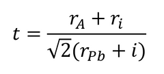
Where ri is the ionic radii, rA is the radius of the cation, and rPb is the radius of the lead molecule.3

Different cation sizes can result in lead halide octahedral distortion and tilting.4 If this tilting is significant, it can shift the phase of the perovskite crystal into an undesirable state for photovoltaic activity. This is represented by the tolerance factor. If the tolerance factor is 1, then this produces a cubic perovskite structure. However, if the tolerance value falls between 0.7 and 0.9, then the tetragonal or orthombic phases can be induced.3, 4 MAPbI3 is tetragonal at room temperature (this change is shown in the figure above).

Formamidinium (FA) has been used as an alternative to MA since it is a similar size to methylammonium as shown in the figure above. However, due to its high tolerance factor, formamidinium lead iodide (FAPbI3) exists in a non-perovskite hexagonal phase at room temperature.4 Although a black perovskite phase can be achieved by heating, this non-perovskite phase becomes more significant over time and limits the stability of a device. This can be compensated by introducing smaller inorganic cations into the perovskite, such as cesium (Cs) and rubidium (Ru). The addition of a small amount of Cs into FA-based perovskites assists the crystallisation of the “black perovskite” phase. When exposed to a humid atmosphere, cesium formamidinium lead iodide (CsFAPbI) perovskites showed almost zero changes compared to the FA-only perovskite, which showed serious decomposition.6 By combining MA and FA cations, a tolerance factor of almost 1 is reached.4
Saliba et al. demonstrated a mixed-halide, quadruple-cation perovskite solar cell that achieved efficiencies of 19% on 0.5 cm2 area, and held 95% of its original performance at 85°C for 500 hours under illumination.7 Using mixed-halide and mixed-cation perovskites, solar cells that have good efficiencies and (relatively) good stabilities can be achieved.
Mixed Halide
Another stoichiometric change that can improve perovskite solar cell stability is replacing iodine with other halides (such as chlorine or bromine). Perovskite crystals are most stable in the pseudo-cubic state (e.g. halfway between cubic and tetragonal), and MAPbI3 creates perovskites in the tetragonal state. Bromine (Br) and Chlorine (Cl) are different sizes to iodine, and therefore create perovskite crystals with a different lattice structure. By varying the ratios of these halides, band structure and stability can be changed.8, 9 For example, MAPbBr3 perovskites have more of a cubic structure compared to MAPbI3 perovskites (like the one shown in the figure below). This is a more stable crystal structure.

Noh et al. (2013) showed that cells containing only iodide have an initially higher power conversion efficiency (PCE) at 35% relative humidity (RH). However, when exposed to 55% RH, the iodide-only cells degrade rapidly whereas the mixed-halide cells (0.2:0.8 Br:I) maintain their initial PCE for up to 20 days.8 However, this study also shows that replacing more than 20% of the iodine with bromine leads to a noticeable reduction in perovskite solar cell efficiency.
Ossila provide a selection of Perovskite inks, precursors and interface materials to help you with your research.
Additives
Many additives have been trialled to increase the stability of perovskite solar cells. Some additives, such as butylphosphonic acid 4-ammonium chloride (4-ABPACl), can form cross-links between adjacent perovskite grains, which reduces moisture vulnerabilities at grain boundaries in the perovskite layer.9 Other additives can provide scaffold structures or nucleation sites to aid in producing uniform films or reducing external penetration.6 Zhou et al. demonstrate that by using a polyethylene glycol (PEG) polymer scaffold, PCEs can be increased and thermal stability is improved in MAPb(IxCl1-x)3 devices.10 It has been suggested that the hydroscopic properties of the PEG can even lead to a self-healing effect, reducing moisture damage.
Studies have indicated that additives (e.g. polyvinylpyrrolidone) can be used to control cluster size in the precursor solution. The addition of acids to the precursor solution can also improve the stability of a perovskite film over time. A more detailed review of additives in perovskites can be found here.6
2D Perovskites
2D perovskites can be made by using larger A-cations (e.g. PEA+) acting as a spacer cation. In pure 2D perovskites, only spacer cations are used, leading to single sheets of separated perovskite crystals – in this case the number of layers (n) of perovskite material is 1. In a 3D perovskite structure, n-> ∞. This is shown in the figure below.
As is often the case with perovskite solar cells, there is a trade-off between efficiency and stability. 2D perovskites are more stable. However, they have a larger band gap compared to their 3D counterparts, so they have poorer optical properties. By mixing different stoichiometric quantities of MAI and spacer cations (like PEAI), the n can be tuned.6 This can be utilised to create 2D-3D hybrid perovskites with enhanced optical properties and stability.


An n=3 layered perovskite achieved an PCE of 4.7% in 2016 and showed no signs of decomposition after 46 days without encapsulation.9 Recently, encapsulated 2D/3D perovskites have sustained PCEs of 11.2% over 10,000 hours in controlled conditions.11
Extrinsic Improvements
Encapsulation
A key element of improving perovskite solar cell stability is the full encapsulation of devices. This will – at least partially – protect them from external degradation catalysts, such as ambient moisture and UV light. A common method of encapsulation is to encompass the cell in a UV-curable epoxy resin, followed by a glass cover slip as shown in Ossila’s “How to Make Efficient Air-Processed Perovskite Devices” video. Some studies have used a hydroscopic substance to absorb moisture before it can reach the perovskite layer. These all significantly improve the solar cell stability.
However, when considering the scalability of perovskites, it is important that devices can be compatible with roll-to-roll processing. There has been promising work looking at polymer encapsulation methods. When encapsulated using polyethylene terephthalate (fully sealed around the device), 10,000-hour lifetimes have been achieved.12 This polymer layer is clearly effective in preventing moisture and oxygen penetration. Additionally, luminescent photopolymers can be used in polymer encapsulations to reduce UV degradation.13 These photopolymers downshift the UV light - which may be absorbed by the perovskite to increase efficiency, and also protects the perovskite. It has been shown that by encasing a perovskite solar cell with a fluoropolymer coating, cells can maintain 3-month lifetimes in outdoor conditions at high efficiencies.13
Summary
Improving the stability of perovskite solar cells is one of the most pressing issues faced by the field right now. Like the causes of degradation, the approaches to increase stability fall into two broad categories. By making intrinsic improvements - for example by changing the perovskite stoichiometry - you can reduce innate vulnerabilities of the perovskite itself. Extrinsic improvements (such as encapsulation) can reduce exposure to degradation factors. However, there is still much work to be done in both these areas to make a reliable and stable perovskite solar cell.
Mary’s notes: In researching this article, I found these reviews very helpful: Reference [4], [6], and [9]. I have tried to summarise key studies discussed in them, but for a more in-depth discussion of the stability processes, these papers are a good place to start.
References
- Conings, B., Drijkoningen, J., Gauquelin, N., Babayigit, A., D'Haen, J., & D'Olieslaeger, L. et al. (2015). Intrinsic Thermal Instability of Methylammonium Lead Trihalide Perovskite. Advanced Energy Materials, 5(15), 1500477. doi: 10.1002/aenm.201500477
- G. E. Eperon, S. D. Stranks, C. Menelaou, M.B. Johnston, L. M. Herz H. J. Snaith, Formamidinium lead trihalide: a broadly tunable perovskite for efficient planar heterojunction solar cells, Energy Environ. Sci., 2014,7, 982-988
- Conings, B., Drijkoningen, J., Gauquelin, N., Babayigit, A., D'Haen, J., & D'Olieslaeger, L. et al. (2015). Intrinsic Thermal Instability of Methylammonium Lead Trihalide Perovskite. Advanced Energy Materials, 5(15), 1500477. doi: 10.1002/aenm.201500477
- Leijtens, T., Bush, K., Cheacharoen, R., Beal, R., Bowring, A., & McGehee, M. (2017). Towards enabling stable lead halide perovskite solar cells; interplay between structural, environmental, and thermal stability. Journal Of Materials Chemistry A, 5(23), 11483-11500. doi: 10.1039/c7ta00434f
- Li, Z., Yang, M., Park, J., Wei, S., Berry, J., & Zhu, K. (2015). Stabilizing Perovskite Structures by Tuning Tolerance Factor: Formation of Formamidinium and Cesium Lead Iodide Solid-State Alloys. Chemistry Of Materials, 28(1), 284-292. doi: 10.1021/acs.chemmater.5b04107
- Emami, S., Andrade, L., & Mendes, A. (2018). Recent Progress in Long-term Stability of Perovskite Solar Cells. U.Porto Journal Of Engineering, 1(2), 52-62. doi: 10.24840/2183-6493_001.002_0007
- Saliba, M., Matsui, T., Domanski, K., Seo, J., Ummadisingu, A., & Zakeeruddin, S. et al. (2016). Incorporation of rubidium cations into perovskite solar cells improves photovoltaic performance. Science, 354(6309), 206-209. doi: 10.1126/science.aah5557
- Noh, J., Im, S., Heo, J., Mandal, T., & Seok, S. (2013). Chemical Management for Colorful, Efficient, and Stable Inorganic–Organic Hybrid Nanostructured Solar Cells. Nano Letters, 13(4), 1764-1769. doi: 10.1021/nl400349b
- Wang, D., Wright, M., Elumalai, N., & Uddin, A. (2016). Stability of perovskite solar cells. Solar Energy Materials And Solar Cells, 147, 255-275. doi: 10.1016/j.solmat.2015.12.025
- Wang, D., Wright, M., Elumalai, N., & Uddin, A. (2016). Stability of perovskite solar cells. Solar Energy Materials And Solar Cells, 147, 255-275. doi: 10.1016/j.solmat.2015.12.025
- Grancini, G., Roldán-Carmona, C., Zimmermann, I., Mosconi, E., Lee, X., & Martineau, D. et al. (2017). One-Year stable perovskite solar cells by 2D/3D interface engineering. Nature Communications, 8, 15684. doi: 10.1038/ncomms15684
- Gevorgyan, S., Madsen, M., Dam, H., Jørgensen, M., Fell, C., & Anderson, K. et al. (2013). Interlaboratory outdoor stability studies of flexible roll-to-roll coated organic photovoltaic modules: Stability over 10,000h. Solar Energy Materials And Solar Cells, 116, 187-196. doi: 10.1016/j.solmat.2013.04.024
- Bella, F., Griffini, G., Correa-Baena, J., Saracco, G., Gratzel, M., & Hagfeldt, A. et al. (2016). Improving efficiency and stability of perovskite solar cells with photocurable fluoropolymers. Science, 354(6309), 203-206. doi: 10.1126/science.aah4046