How to Set Up Your Solar Simulator Light Source
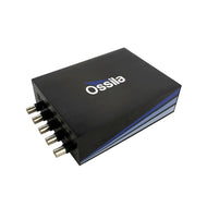
The Ossila Solar Simulator is available in two configurations. The automated set up which uses the automated Ossila Solar Cell I-V Test System with a fitted test board. It can also be configured using the manual test board in combination with the Ossila Source Measure Unit. This guide details how to assemble the manual Ossila Solar Simulator.
Solar Cell Testing Kit

- Unbeatable Value
- Easy Cell Characterization
- Intuitive Software
Worldwide Delivery £3800
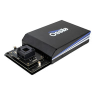
Positioning the Light Source
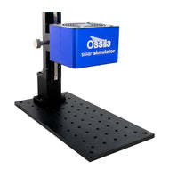
The solar simulator light source is compact, lightweight and can be easily installed in any lab using adjustable height stand provided with it.
First, position the base of the solar simulator stand on the optical breadboard. Align the base holes with the threaded holes on the breadboard and fix in place. Attaching the solar simulator to a breadboard will ensure that the relative position of all lamp components stay fixed and will balance the light source. Make sure to position the base to allow enough room to put the test board under the lamp when fully assembled.


Next, align the holes in the bottom of the adjustable stand and use four screws to secure the stand to the base. It is important that this the position solar simulator light source remains fixed, so ensure both the base and the stand is fixed in place.


On the adjustable height stand, there is a square plate with threaded holes in the corners. Screw two of the smaller screws into the two lower holes. Use these lower screws to support the lamp while you align and screw in the upper two screws. Again, reducing lamp movement is very important, so ensure this is fixed into place.


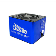
Plug in power supply to the light source and switch on. The LED next to the power button will be white when the lamp is reaching the correct intensity. It will turn green when it has reached 1 Sun. This will happen quite quickly, but we recommend waiting for at least 5 minutes to ensure temporal stability.


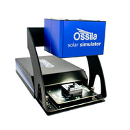
One of the most important things to remember when setting up the manual Ossila Solar Simulator is to make sure there is the correct distance between the top of your sample and the light source. This is important as solar simulators have to meet specific classifications to represent sunlight uniformly. This calibration is usually confirmed within a certain radius of the solar simulator light source. For this reason, the Ossila bottom solar simulator light source should be positioned 8.5 cm away from the surface of your sample.

For example, with Ossila push fit test board, the lid means that the surface of the sample is 5.75 mm below the "top" of the board. This should be taken into account, and the 8.5 cm should be measured from this point.
Different test boards or measurement stages may have different heights and therefore, we have made the Ossila Solar Simulator that the height can be adjusted. Once the lamp is fixed to the adjustable stand, you can adjust the height using the knob on the side of the adjustable stand.