Optical Spectroscopy
Optical spectroscopy (or UV-Vis spectroscopy) is a versatile, non-invasive technique widely used to study a range of different materials. Useful for probing solutions, thin films, or bulk devices, it can help you determine the material properties and molecular structure of your sample. You can also use optical spectroscopy for several biological and industrial applications.
Fairly easy to set up, all you need to begin is an optical spectrometer and a calibrated light source. The type of optical spectroscopy you should do will depend on both your sample and the material property you wish to investigate. Additionally, the type of light source you need will also depend on the type of spectroscopy you wish to perform.
The main types of optical spectroscopy are photoluminescence, absorbance, and reflectance spectroscopy, which measure how a sample emits, absorbs, and reflects light, respectively.
Optical Spectroscopy Kit

- Excellent Value
- Free Software
- Worldwide Shipping
Buy Online £2400
What is Optical Spectroscopy?
In broad terms, optical spectroscopy uses light in the UVA, visible, and IR regions of the electromagnetic spectrum (anywhere between 190 - 1000 nm) to probe materials. By directing a light source through or reflecting it off a sample, you can use an optical spectrometer to measure how this light interacts with the sample. The spectrometer outputs the intensity of the measured light as a function of wavelength, and from this, you can gain important information about the electronic structure of your material.
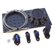
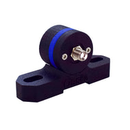
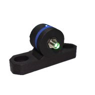
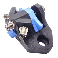
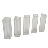
A typical spectroscopy set up consists of a spectrometer, the sample (usually held in either a transmission holder or cuvette holder), and a light source. These may be connected together with optical fibers ("coupled") and/or bolted to an optical table or breadboard plate. You can perform optical spectroscopy using a range of different light sources, categorised as either monochromatic or broadband sources. The type of measurement you wish to take determines which light source you should use. In general, monochromatic sources are used to excite materials (for example, in fluorescence measurements) whereas broadband sources are used for absorption, transmission and reflection measurements.
Within an optical spectrometer, a dispersive element (for example, a prism) splits incoming light into its integrant wavelength components. This light is then directed onto an optical sensing element, which measures the intensity of light at each wavelength. By directing a calibrated light source into a spectrometer after it has passed through a material, or reflected off a sample, you can directly measure how your sample interacts with light. You can use this information to indirectly measure other material properties, such as the concentration of a molecule in your sample.
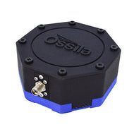
To get started with the Ossila Optical Spectrometer, simply plug it in to a computer via the supplied USB-C cable and launch the spectroscopy software. The spectrometer can be controlled via serial commands (please see the optical spectrometer user manual for details) but the spectroscopy software is the easiest way to interface with the device, take measurements, and save and analyse data.
We recommend waiting for around 30 minutes for the internal temperature of the spectrometer to stabilise before taking any measurements.
Ambient light
We recommend performing measurements in the dark where possible. This reduces the effects of ambient light, which can interfere with spectroscopic measurements. The measurement apparatus (i.e. spectrometer, light source, and sample holder) should also be firmly secured (e.g. on an optical breadboard) before starting measurements. This is because any changes in position during the measurement will affect the results.
Jablonski Diagrams
The most common way to illustrate electronic and vibrational states and the transitions between them is using a Jablonski diagram. Here, the energy levels are arranged vertically according to their energy and horizontally according to multiplicity. An example Jablonski diagram is shown below.
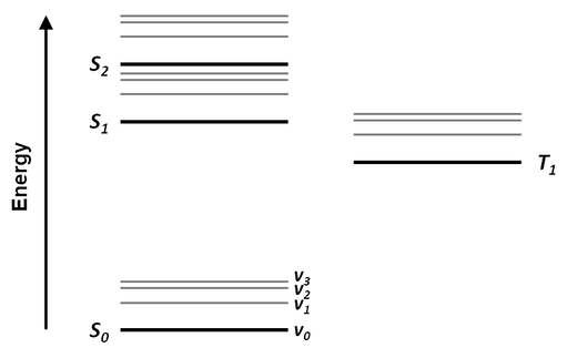
Radiative transitions (such as absorption and fluorescence) are indicated by straight arrows, while non-radiative transitions (such as internal conversion and intersystem crossing) tend to be indicated by wavy arrows.
Types of Optical Spectroscopy Measurements
Transmittance
Transmission measurements allow you to quantify how opaque a sample is to a particular wavelength of light. The transmittance, T , of a sample is defined as the ratio of light incident on the sample, I0 , to the intensity of light emerging from the other side of the sample, I:
This technique is complementary to absorbance spectroscopy, as you can work out the absorbance spectrum of a sample from the transmittance spectrum. You can also use transmittance spectrometry to measure the optical transparency of materials. For example, in the case of optoelectronic devices, the top contacts and top facing transport layers should be transparent in the visible region. This works to reduce parasitic absorption.
For transmittance measurements, light from a broadband light source is transmitted through a sample, and is then is detected by an optical spectrometer.
Absorbance
Optical absorption is a measurement of the attenuation of light as it passes through a material. As light travels through a material, the energy of the incident photons can transfer electrons into higher energy states. In other words, electrons in the material absorb this light. In most optically active materials, UV and visible photons will promote electrons to higher energy electronic orbitals, while IR photons will increase the vibrational energy of the electrons.
Different electrons in different atomic configurations will absorb different wavelengths of light. Therefore, absorption measurements are very useful for a wide range of applications as they can provide a "finger print" of the material you're looking at. Depending on the sample, measuring absorption with optical spectroscopy can tell you many things about your sample. Some examples include:
- Electronic structure and the properties of molecules in a solution or thin film.
- Volume concentration, film thickness or molar concentration.
- Optical density of bacterial cultures (used to monitor bacteria growth).
You can also use this technique as a non-invasive means of tracking changes in systems or materials (i.e. phase changes, glass transitions in polymers, or changes in pH of some solvent systems).
To take absorption and transmission measurements, light is directed towards the spectrometer and a spectrum is taken either with no sample in place, or using a reference placed in between the light source and spectrometer. For example, if the sample is in solution, a cuvette containing the pure solvent can be used as the reference. If the sample is a thin film on a substrate, a blank substrate is usually used. The reference is then replaced by the sample and another spectrum is taken. The transmission and (assuming no reflection) absorption spectra can then be calculated.

Photoluminescence
Photoluminescence spectroscopy measures the photoluminescence of a sample. This is when a sample or material absorbs electromagnetic energy in the form of a photon and then emits this energy in the form of another, lower-energy photon. This is also known as radiative emission or radiative recombination. PL spectroscopy is complementary to absorbance spectroscopy. Unlike chemiluminescence or electroluminescence, one key feature of photoluminescence is that it requires the absorbance of a photon.
You can use photoluminescence to investigate key electronic properties of different materials. It is useful for testing optoelectronic and photonic devices. Common uses of PL spectroscopy include:
- Studying the optical properties of materials used in electronic devices, i.e. solar cells, LEDs.
- Characterising semiconductors.
- Studying biological samples.
Photoluminescence should occur isotopically, so you can measure the PL spectrum of a sample at various angles. This means that you will need to optimise the design based on your sample. In all cases, you should use a high-energy light source, either UV laser or UV monochromatic light sources. This will excite the electrons into their excited states, and the spectrometer will detect the emitted light. You may need to use a filter to remove the laser signal.
There are two main types of photoluminescence: fluorescence and phosphorescence.
Fluorescence
Fluorescence involves the relaxation of an electron through a singlet-singlet transition and happens on a nanosecond timescale. This means that once an electron has absorbed a photon, it almost immediately relaxes and re-emits another, lower-energy photon. This short lifetime means that fluorescence emission occurs only while the sample is being illuminated.
Phosphorescence
Phosphorescence occurs over a longer time scale. Phosphorescence requires a triplet-singlet transition, which is much less likely to occur than a singlet-singlet transition. The longer lifetime of phosphorescence means that phosphorescent materials emit light continuously after being illuminated. Therefore, these materials glow.
Chemiluminescence
Chemiluminescence is when a sample emits a photon because of a chemical reaction. This occurs when the chemical reaction creates a product which is in an excited state. This product then returns to its ground state through the emission of a photon or through the transfer of energy to a luminescent material. Like phosphorescence, this causes the material to glow. However, unlike photoluminescence, there is no initial illumination to cause this excited state.
We often see this process in nature—for example, in glow worms, fireflies, and jellyfish. It also has extensive biological applications, such as acting as labels for immunoassays or probing DNA. You could also use chemiluminescence for synthetic purposes, such as creating glow sticks or detecting pollution levels in the atmosphere.
Electroluminescence
Electroluminescence is the emission of light in response to an electric current or electric field being applied across the material. This is used in optoelectronic materials, often semiconductors. Excess electrons are injected into excited states by doping the material (e.g. to create a p-n junction), or by applying a strong electric field across it. These electrons then relax back to their ground state, emitting a photon.
Electroluminescence is used in dashboard displays and in some nightlights. However, the most common use of electroluminescence is in light emitting diodes.
Diffuse Reflectivity
Reflectance spectroscopy studies the way that light scatters off a surface or sample. There are many types of reflectance spectroscopy, but the two main types are specular and diffuse reflection. Specular reflectance is used to measure more ideal reflectors, such as mirrors. It can be a useful property to examine when you are determining a material's suitability for a certain use. Diffusive reflection measures the way light reflects or scatters off a textured or rough surface.
Contributing Authors
Written by
PhD Student Collaborator
Reviewed by
Product Specialist
Application Scientist
Related Products