Dip Coating: Practical Guide to Theory and Troubleshooting
Dip coating is a simple and effective technique which is commonly used in manufacturing across a wide range of different industries. Within research and development, it has become an important coating method for the fabrication of thin films using a purpose-built dip coater. When the process is optimised, dip coating can be used to produce highly uniform films. Importantly, key factors such as film thickness can be easily controlled.
One advantage of dip coating over other processing techniques is the simplicity of its design. It is low-cost to set up and maintain, and can produce films with extremely high uniformity and a roughness of nanometres.
Dip coating is a relatively straight-forward technique. However, in order to achieve maximum control when coating a substrate, it is important to be aware of what can affect your results. To make high-quality films, parameters such as withdrawal speed must be optimised. Atmospheric factors including temperature, airflow, and cleanliness also play a big part in film quality and must be closely monitored during the dip coating process; a glove box is a useful system for controlling atmospheric conditions. As with other methods, defects can occur, but by understanding the underlying causes it is relatively easy to find the root of the problem and take appropriate action.
This guide is a practical introduction to dip coating. It discusses fundamentals including the formation of the wet film, thickness evolution, drying dynamics, and how processing conditions can affect the processes that occur during dip coating and ultimately impact the final film thickness. The most common issues that you might encounter are also explained.
Contents
- Overview of Dip Coating
- Dip Coating Theory
- Withdrawal and Film Formation
- Viscous Flow and Drainage Regime
- Drying Dynamics
- Capillary Regime
- Thickness vs Withdrawal Speed
- Minimum Film Thicknesses Equations
- Withdrawal Speed
- Troubleshooting Defects
- Stripe Defects
- Visible Particles, Pinholes, & Craters
- Partial/Inhomogeneous Coating
- Cracking Defects
- Running/Curtaining
- Further Reading
Overview of Dip Coating
Dip coating involves the deposition of a liquid film via the precise and controlled withdrawal of a substrate from a solution using a dip coater. The dip coating process involves a minimum of four unique steps (or stages) followed an optional fifth curing step:
- Immersion
- Dwelling
- Withdrawal
- Drying
- Curing (Optional)
All these stages are essential in the dip coating process. However, the two critical points for determining the properties of the deposited film are the withdrawal and drying stages. The final film thickness is determined during these stages by the interplay between the entraining forces, draining forces, and the drying of the film. Films are formed in one of three regimes:
- Viscous flow
- Drainage
- Capillary
The transitions between each of these regimes occur at varying values of withdrawal speed and solution viscosity. The combination of the three coating regimes ultimately determine the 'thickness vs withdrawal speed' behaviour for a thin film. By summing the contributions from the drainage regime and capillary regime, it is possible to obtain an equation that explains the thickness withdrawal speed relationship over a wide range of speeds. This also allows us to determine the minimum possible thickness that can be coated for a solution.

The figure above shows a simplified way in which the liquid film forms when a substrate undergoes the dip coating process. The substrate is lowered into a bath of solution until it is mostly or fully immersed. A short delay occurs before the substrate is withdrawn. During the withdrawal process, a thin layer of the solution remains on the surface of the substrate. Once fully withdrawn, the liquid from the film then begins to evaporate and leaves behind a dry film. For certain materials, a further curing step can be performed which forces the deposited material to undergo a chemical or physical change.
Dip Coater

- High Precision
- In-built Software
- Wide Speed Range
Available Now £2500
Dip Coating Theory
Withdrawal and Film Formation
The withdrawal stage of the dip coating process can be simply seen as the interaction of several sets of forces. These forces can be placed into one of two categories: draining forces and entraining forces. Draining forces work to draw the liquid away from the substrate and back towards the bath. Conversely, entraining forces are those that work to retain fluid onto the substrate. The balance between these sets of forces determines the thickness of the wet film coated onto the substrate. During the withdrawal stage, the formation of the wet film can be broken into four regions (shown in the figure below).

These four regions are:
- The static meniscus, where the shape of the meniscus is determined by the balance of the hydrostatic and capillary pressures.
- The dynamic meniscus, which occurs around the stagnation point. The stagnation point is where the entraining forces and draining forces are in equilibrium.
- The constant thickness zone, where the wet film has reached a given thickness (h0).
- The wetting zone, which is the region where the wet film begins.
The dynamic meniscus and the flow of solution in this region determine the wet film thickness. Therefore, understanding the physics that underpins the curvature of the dynamic meniscus and the thickness of the stagnation point are important.
The figure below shows the dynamic meniscus region. The transition between the static and dynamic meniscus occurs within the boundary layer (L). In this region, the forces from viscous flow impact the way the solution moves. Beyond the boundary layer, the draining forces are significantly greater than those of the viscous forces. In this region, it is the balance between the hydrostatic and capillary pressure that determines the meniscus.
The stagnation point occurs when the balance between the entraining forces and the draining forces are equal. It is the balance of these forces that determine the film thickness. There are three different coating regimes that are defined by which forces dominate the behaviour of the coating - these are the viscous flow, draining, and capillary regimes.

Viscous Flow and Drainage Regime
The first coating regime is the viscous flow regime. This occurs for high velocities and viscous solutions. Here, the coating is dominated by viscous forces and gravitational attraction. In this case, the thickness of the liquid layer can be given by Equation 1.
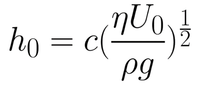
Here, the entraining force is made up of the viscous forces acting on the solution as the substrate is withdrawn. This is given by the viscosity (η) and the rate of withdrawal speed of the substrate from the solution (U0). The draining force is that of gravity, given by the density of the solution (ρ) and the gravitational constant (g). The constant (c) is related to the curvature of the dynamic meniscus. This constant is a property of the solution itself, and is strongly related to the rheological properties of the solution. For most Newtonian liquids, this constant is around 0.8.
In most situations, the withdrawal speeds or the viscosity of the solutions used will not be high enough for this approximation to be valid. When these two variables are reduced, the viscous force becomes weaker. The balance between the entraining forces and the draining force is then also dependent upon surface-tension driven movement of the solution. It is under these conditions that the coating is said to be within the drainage regime. The Landau-Levich equation (refer to Equation 2) describes the relationship between the wet film thickness and the withdrawal speed of the substrate (when surface tension is considered).

The Landau-Levich equation is valid until very low withdrawal speeds are considered. When the speed is reduced to lower than approximately 0.1mm.s-1, a third regime of coating occurs. This regime is known as the capillary regime. In the capillary regime, the rate at which solution is entrained onto the substrate (through viscous flow) is lower than the rate of evaporation. Therefore, the dynamics of drying are crucial to understanding the capillary regime.
Drying Dynamics
Dip coating typically has three different stages for drying:
- Drying front during coating
- The constant rate period
- The falling rate period
The simplest drying stages are the constant rate period and the falling rate period. The constant rate period occurs within the constant thickness zone (during and after coating). Here, evaporation of solvent happens at the surfaces of the wet film and occurs uniformly across it. The only exception to this is at the edges of the substrate, where the drying front occurs.
Over time, most of the solvent will be removed from the wet film until a gel-like film is formed. This is when the falling rate period occurs. In the falling rate period, the small amount of solvent left becomes trapped within the gel - and the evaporation is determined by the diffusion of solvent towards the surface.
The more complex drying stage occurs at the drying front is shown in the figure below. The drying front appears at the interface between the wet film and substrate - the most obvious one being at the wetting zone. Due to the greater surface-area-to-volume, evaporation occurs much faster here, leading to the formation of a wet film with higher concentration. This results in the drawing of solution from the surrounding areas due to surface-tension driven effects. Once the solution at the drying front forms a dry film, a capillary force will be exerted on the solution. This causes the solution to wick into the dry film - resulting in the thickening of the deposited film.
Solution being drawn into the drying film (because of the capillary force) occurs during the capillary regime of coating. For fast enough withdrawal speeds, the rate at which the drying front recedes is significantly lower than the formation of the constant thickness zone. Therefore, the drying dynamics are dominated by the constant rate period, and the final film thickness will be dependent upon the initial wet film thickness. For slow withdrawal speeds (where the drying front recedes faster than the rate of withdrawal), the drying dynamics are dominated by the drying front.

Capillary Regime
In the capillary regime, the wet film thickness is not considered. This is because a constant thickness zone is never truly achieved at these coating speeds. In the capillary regime, the final thickness is therefore dependent upon i) the rate of withdrawal, ii) the properties of the solution, and iii) the evaporation rate of the solvent. The dry film thickness is therefore given by Equation 3.
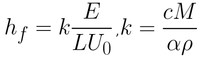
Here the evaporation rate (E), the width of the coated film (L), the withdrawal rate (U0), and the materials proportion constant (K) determine the final dry film thickness (hf). K is a combination of solute, solution, and dry film properties. The constant is due to the total concentration of the solute in solution (c), the molar weight of the solute (M), the density of the solute (ρ), and the porosity of the deposited film (α).
Properties such as concentration of solute, density of solute, and molecular weight of the material have a simple and obvious impact on the dry film thickness. However, the porosity value is significantly more complex. Not only does the porosity vary the density of the film in comparison to the raw material itself - it also impacts the drying dynamics. As mentioned previously - at the drying front, at the point of contact between the dry film and the wet film, the wet film will be drawn into the dry film via capillary action. The porosity of the film also strongly influences this, determining the rate at which solution will be drawn into the dry film, the distance into the dry film it will go, and the rate at which this absorbed material will dry.
Film Thickness vs Withdrawal Speed
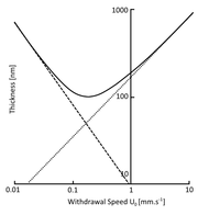
The dry film thickness as a function of withdrawal speed requires both the Landau-Levich equation and the capillary regime equation to be used. The figure below shows an example withdrawal speed vs film thickness graph for the dip coating process. A minimum thickness for dip coating is achieved during the crossover between these two coating regimes. As the withdrawal speed goes away from the minimum in either direction, the different coating regimes dominate.
For high and low speeds, the thickness curve can be given by either the Landau-Levich equation or the capillary regime equation alone. However, for a range of coating speeds, neither equation alone can give accurate values for the coating thickness. This occurs at the absolute minimum for coating thickness. To calculate the minimum thickness, you need an equation that unifies both the Landau-Levich and the capillary regime equation. This will be discussed in the section below.
Minimum Film Thickness Equations
To determine the minimum thickness, both the equations governing the thickness during the drainage regime and the capillary regime must be combined. The first step in this is modifying Equation 2 to relate the wet film thickness to the dry film thickness. This can be done simply by including the 'materials proportion' constant into the equation.
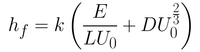
Summing up both equations gives you Equation 4. Here, the first term in the bracket is related to the capillary regime (Equation 3) while the second term is related to the drainage regime (Equation 2). The constants seen in Equation 2 have been rolled into a universal solution constant (D).
From this equation, it is possible to determine the smallest film thickness by differentiating the thickness with respect to withdrawal rate. By setting this derivative at 0 (which is the gradient at the inflection point of the minimum), you get Equation 5.
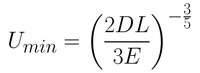
Although this equation gives a close approximation to the actual film thickness achieved, there are several contributing factors that have not been considered. These include air flow at the surface, variable evaporation rates, viscosity and concentration gradients, thermal gradients, Marangoni flow and other parameters that can vary over time.
Changing Withdrawal Speed
The meniscus is defined by two main forces:
- Gravitational-based viscous drag
- Surface forces between the substrate and the solution
During withdrawal of the substrate, the solution (hereby referred to as ink) in the meniscus will either fall back into the reservoir or be pulled up with the substrate to make a film, as shown in the figure below. The meniscus terminates at the drying line. This is the point at which all the solvent has evaporated or drained, leaving a solid film. The drying line moves at the same rate as the withdrawal speed. As the substrate is withdrawn, the meniscus stays near the substrate-reservoir boundary, effectively “moving down” the substrate. With dip coating, there are two main regions defined by withdrawal speed: the capillary region (low speed) and the draining region (high speed).

In the draining region, withdrawal speeds are higher than 1mm/s. The drying line is moving faster than the solvent is evaporating. Here, film thickness is governed by the ink properties and the withdrawal speed, according to the Landau-Levich model. Evaporation rate does not factor heavily here.
In the capillary region, withdrawal speeds tend to be lower than 0.1mm/s. The key factor here is that the evaporation rate is faster than the "movement" of the drying line. Here, as soon as the ink is fed into the upper part of the meniscus, the solvent is evaporated. It is then replaced as surface forces pull more ink up the substrate - and again the solvent is evaporated. This is capillary feeding. Therefore, in this region, the lower the withdrawal speed is, the thicker the film.
There is a region in between these which can be accurately modelled by a combination of the models above. This region produces the thinnest film and defines a V-shaped dependence of thickness on withdrawal speed, shown in the figure below. Working in the capillary region can cause some issues outlined in this guide - so if possible, it is better to work with higher withdrawal speeds. However, if the coating ink is very diluted, it may be necessary to use low withdrawal speeds to achieve a uniform coating.

Troubleshooting Dip Coating Defects
Dip coating defects can broadly be classified into two main categories based on the two main things that dip coating is vulnerable to. These categories are:
- Defects due to instabilities in the dip coater or variation of withdrawal speed
- Defects due to "external" factors such as the atmosphere the substrate is coated in or the viscoelastic and chemical properties of the ink
There are a number of methods that can be used to prevent defects when dip coating thin films. The following section discusses commonly-occurring problems and defects including the characteristic features that can be used to identify them, why (and from where) they arise, and how they can be rectified.
The most important things to observe when troubleshooting defects are:
- Where the defects occur
- Frequency of the defects
- Defect size & shape
- When in the coating process they occur
Using this information, a defect can easily be spotted, identified, and eliminated. Once all parameters are noted and optimised, users can begin making uniform, high-quality films using the dip coating method.
Stripe Defects
This section discusses "stripes" across the film, orientated perpendicularly to a substrates withdrawal as shown in the figures below. This defect appears at regular intervals along the coated substrate.
The characteristics of stripes are:
- Bands of thicker film (forming horizontal stripes), perpendicular to withdrawal direction.
- Can appear as colour variation or structured inhomogeneity in the film thickness.
- The defect will occur at roughly evenly-spaced intervals or frequencies.
The origin of this dip coating issue is usually due to low withdrawal speed. An example of this can be seen below.

Low Withdrawal Speeds
Films produced in the capillary region can exhibit specific defects due to the "coffee-ring effect". If ambient temperatures are high, evaporation rates are also high. Solvent at the edge of the meniscus evaporates first, leaving the solute deposited. Due to capillary feeding, as soon as the solvent has been evaporated, more ink replaces it. The edge is therefore “pinned” here as seen in the figures below.
As a result of this, more solute is deposited at the edge of the meniscus, so the film will be thicker in these regions. As the substrate is moved upward, this pinned edge is separated from the meniscus. The meniscus moves down until the edge is pinned again. These “stripes” will be periodic, as this process will keep repeating.


There are two ways to reduce this effect: increase the withdrawal speed, or reduce the ambient temperature. Thick films can be produced in both regions, but these “coffee-ring” effects are only seen in the capillary region. By increasing the withdrawal speed, you negate this problem. To enter the draining region, withdrawal speeds of over 1mm/s are recommended. If you are using a particularly diluted ink, this may also involve increasing the concentration to achieve a uniform coverage on your film. It must be noted that there is an upper limit in regards to withdrawal speed – see running and curtaining for more information on this.
Alternatively, if you cannot change the concentration, this effect can be lessened by reducing temperature. Reducing temperature reduces evaporation rate, therefore lessening the capillary feeding. However, this could still lead to inhomogeneity in the film, evident by a colour variation. Another alternative is to use an alternative solvent (that the solute is dissolved in) with a higher boiling point, in order to further reduce the evaporation rate of the solvent.
Visible Particles, Pinholes, & Craters
This section discusses visible defects that can be seen in the film's microstructure. There are three main types of defects: visible marks, pinholes, and craters. An example of these effects can be in the figures below.
There are several signs that there could be defects on a film, such as:
- Visible particles on the film's surface.
- Optical properties of the film could be affected (e.g. transparent coating appearing ”hazy”)
These defects can be caused by many things, including:
- Dust or contamination on the substrate before coating
- Aggregation or crystallisation of the solute
- Evaporation cooling effects


Dust or contamination on the substrate before coating
The presence of small particles (often visible) can be the cause of defects in the film. Solution can form comet-like trails behind the particles, or the particles can act as sites of aggregation. Even if the small particles are removed before the film is deposited, this contamination could still lead to pinholes. Previous contamination can change the surface energy of a substrate, leading to inefficient wetting in this area - creating a pin hole, where the film is thinner.
Therefore, it is important to thoroughly clean the substrate before deposition. Cleaning substrates for dip coating requires a similar process to the one used in spin coating. Initially, it is best to clean the substrate with an electronic grade cleaner, (such as Hellmanex III), and a semi-polar solvent (such as acetone/IPA). This ensures that there are no dust particles or other residues left on the substrate. Secondly, when coating a substrate, it is useful to chemically prepare it, by exposing active “-OH” terminations to aid effective wetting. This involves cleaning it with an NaOH solution or an oxygen plasma / UV Ozone cleaner. The substrate must then be stored in a clean environment to reduce further contamination.
Aggregation in Solution
Depending on the inks used, aggregation or crystallisation of the solute may have occurred. This happens for materials that are weakly soluble in the solvent used. Additionally, solutes may aggregate or crystallise during the dip coating process, instead of forming an even film.
If crystallisation has occurred before deposition, it may be possible to redissolve by heating the ink. Additionally, inks should always be filtered before use to remove any contamination. The pore size used in the filtration should be roughly the same as the thickness of the film, to reduce any visible contamination. Pore sizes of around 2µm are recommended, but smaller can be used if necessary. If the inks are being stored, they should be regularly filtered.
Evaporation Cooling Effects
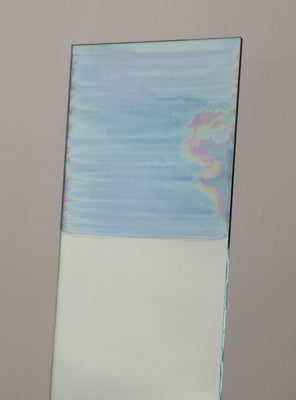
The evaporation of solvents during the drying phase cools both the substrate and the film. This cooling could lead to several problems during subsequent film formation, leaving crater-like marks in the fine structure of the film. On a macroscale, this can create a hazy coating where there should be a transparent one as seen in the figure below.

This effect can be reduced by heating the ink before deposition takes place. Even heating from room temperature to 25°C can increase film uniformity drastically. Also, it is important to leave the substrate in the ink for a period of 30-60 seconds during immersion. This allows it to reach thermal equilibrium with the ink. During withdrawal, the substrate can then store this heat, further reducing the effect of evaporation cooling.
Partial or Inhomogeneous Coating of the Substrate
An advantage of using dip coating is the level of uniformity that can be achieved. This section discusses the factors that can lead to inhomogeneity in a film when dip coating.
Characteristics of an inhomogeneous film include:
- Colour variation appear across the coated substrate
- Thickness variation occurs across the film


The origin of inhomogeneity could be due to:
- Insufficient Wetting
- Turbulent Airflow During Drying
- Inconsistent Withdrawal Speed
- Meniscus Height Issues
Insufficient Wetting
One way to characterise a ink's wettability (whether it will spread across a substrate) is by using contact angle analysis. A small contact angle means a liquid has high wettability with a substrate. In other words, it will spread well as seen in the figure below.

Contact angle depends on two things: the surface tension of the liquid and the surface energy of the substrate. If the surface tension of the liquid is high, the molecules will have a strong attraction to each other, this results in dewetting. While if the surface energy is high, the liquid molecules will have a greater affinity towards the substrate resulting in wetting.
If either the surface energy of the substrate is too low, or the surface tension of the ink is too high, the ink will not sufficiently coat the substrate. The meniscus formed in dip coating comes from a balance between gravitational-based “draining” forces and surface-tension-based “capillary” forces. If the ink is more attracted to itself than it is to the substrate to begin with, then it will be challenging to achieve uniform coating of the substrate.
In this situation, it is often best to change the solvent to one with a lower surface tension, use a surfactant, or treat the substrate to increase its surface energy (i.e. with an oxygen plasma). The latter is not recommended for organic-based transistors where a low surface energy is needed for optimal performance.
Turbulent Airflow During Drying
During the drying phase, the wet film is extremely sensitive to external factors, especially airflow. Turbulent airflow can affect evaporation rates, and subsequently drying rates, leading to inhomogeneities. No airflow over the substrates can also cause problems during drying. A tell tale sign of this is the inhomogeneity will not show an obvious pattern, but may form "streaks" of thicker or thinner film.
It is best if the substrate is exposed to constant laminar flow during drying, so that factors like evaporation rates can be kept consistent. However, caution must be taken, as with airflow can come contamination - which the film is also vulnerable to during the drying phase. It is important that this stage takes place in a clean environment. We recommend using a laminar flow hood to ensure your environment is free of dust and microbial contaminants.
Inconsistent Withdrawal Speed
Thicknesses of films created in dip coating are dependent on withdrawal speed. Therefore, if the withdrawal speed is not consistent, this will lead to thickness variations in the film. If this happens, the thicknesses would only vary parallel to the withdrawal direction. Thicknesses across the substrate (perpendicular to withdrawal direction) would be consistent. This is illustrated in the figure below.

Meniscus Height Issues
For low withdrawal speeds, film thickness is dependent on evaporation rate. This, in turn, is dependent on the ambient conditions surrounding the film. As the substrate is submerged, and if the reservoir is too full, the meniscus may go higher than the reservoir, as seen below.

Evaporation happens at the meniscus edge for very low withdrawal speeds. This meniscus is effectively exposed to two different atmospheres: one inside the reservoir and one above the reservoir. This could lead to different evaporation rates, and thus different film thicknesses. If a thickness profile shows a peak in thickness at the initial point of film formation (see the figure below), this is probably the error. To reduce this effect, it is important to ensure that the depth of the solution remains relatively constant. Therefore, the volume of solution must be significantly greater than the volume of the substrate.

Cracking
Cracks can often be seen in a thin film after post-deposition heat treatment. This section discusses cracking in thin films. The characteristics of cracking are:
- Long, straight cracks on microscale of film structure
- The amount of cracking will increase with film thickness

The causes of this defect could be:
- Small particles on the film surface
- Loss of water/organics during deposition
- Thermal expansion mismatch
Small Particles on the Film Surface
A main cause of cracking in thin film formation comes from contamination during the “wet” stages. These will create structural weak points, which may put additional stress on the film during heat treatment. As mentioned before, films should be prepared in a clean environment, ideally while exposed to laminar, clean airflow. It should be noted that the cracks caused are far more significant if film thickness is above the critical thickness.
Loss of Water/Organics in Film
During dip coating, there is a substantial volume change from the initial liquid layer to a solid layer. This can lead to significant cracks developing, due to the viscoelastic relaxation of the film during heat treatment. These effects are observed if the film is above a certain thickness – the critical thickness. For example, if small particles have contaminated the film during the initial drying stage and the film is thicker than the critical thickness, significant cracks will form. The critical thickness is different for each ink and can be found experimentally.
Thermal Expansion Mismatch
Cracks may form if the substrate and ink have largely different thermal expansion coefficients. Since the substrate will not expand/contract at the same rate as the film, this places stress on the bonds linking them. This may cause these bonds to break. It is therefore important to use a substrate with a similar thermal expansion coefficient to the ink (where possible). All these problems are dependent on film thickness. In general, the thicker the film, the more cracks will appear. Where possible, it is advantageous to have thinner films. However, if thicker layers are needed, it may be beneficial to apply multiple thin layers with annealing after each one. It must be noted that applying multiple layers may affect the microstructure of the overall film.
Running (Curtaining)
During the drying stages of deposition, the ink can be seen to run. This running is also sometimes referred to as "curtaining", and is in part due to long drying times caused by large wet film thicknesses. In the drainage regime, the film thickness increases with withdrawal speed. Due to the greater volume of solvent, thicker films will have longer drying times. The increased drying time increases the chance that deposited ink could begin to run before it dries, leading to an uneven film distribution.
This would normally happen over speeds of roughly 15mm/s, and with solutions with low viscosity. By modifying the viscosity of the solution, it is possible to reduce the chance of running of the wet film during the drying process. Another method of reducing running is to increase the drying rate of the film - this can be done by using a form of annealing chamber which rapidly dries the film after coating.
Further Reading
For more information on different aspects of dip coating, we recommend the following bodies of work:
- Review Article: Withdrawing a solid from a bath: how much liquid is coated? E. Rio, & F. Boulogne.
- Book: Sol-Gel Technologies for Glass Producers and Users. M. A. Aegerter, & M. Mennig.
- Book: Chemical Solution Deposition of Functional Metal Oxide Thin Films. T. Schneller, R. Waser, M. Kosec, & D. Payne.
Contributing Authors
Written by
Product Developer
Application Scientist