LED Measurement System
Reliable and intuitive PC software, designed to help speed up your research, is provided at no extra cost. The latest versions are always available to download via our website.
Ossila LED IVL 3.0.1
The latest version of the measurement software for the LED Measurement System.
Download (60.1 MB)
Minimum System Requirements
Operating System Windows 10 or 11 (64-bit)
CPU Dual Core 2 GHz
RAM 4 GB
Available Drive Space 171 MB
Monitor Resolution 1440 x 960
Connectivity USB 2.0, Ethernet (requires DHCP)
Simplify LED IVL characterisation for rapid results
A long-term and low cost LED characterisation and lifetime measurement system
Overview | Specifications | Gallery | Software | In the Box | Accessories | Resources and Support
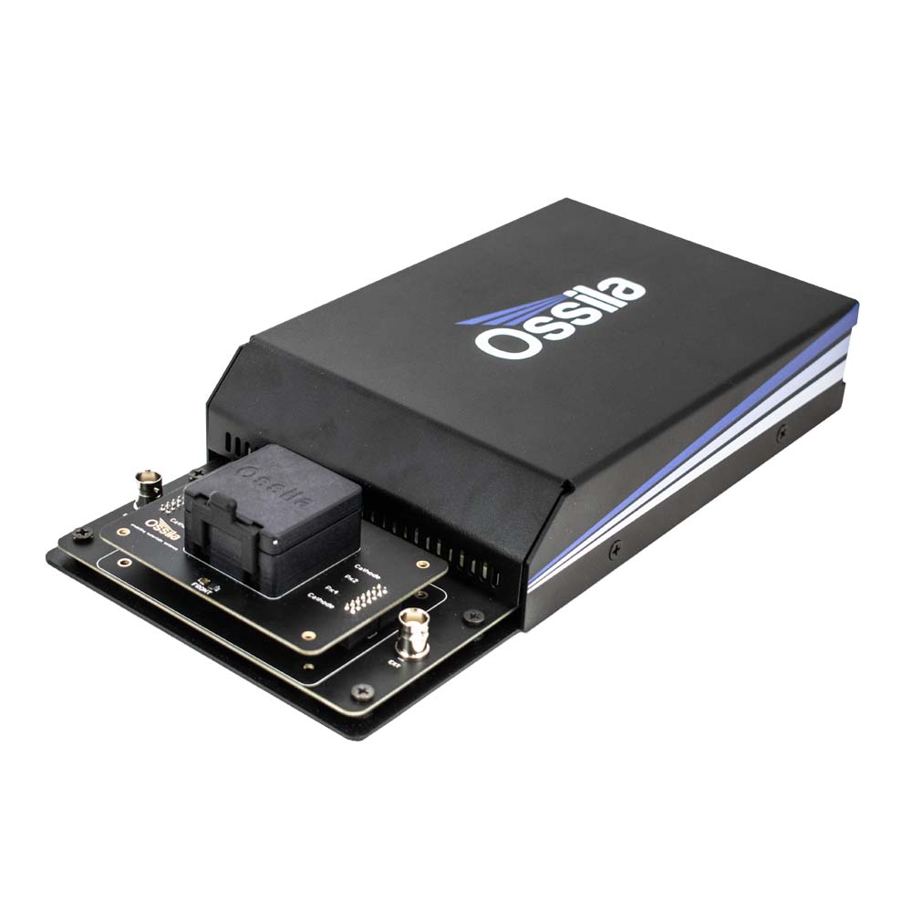
The Ossila LED Measurement System provides a low cost and complete solution for performing current-voltage-luminance (IVL or JVL) characterisation of LEDs. The device holder has built-in light sensors to allow for illuminance, luminance, and white count measurements. To simplify device testing, the software will also calculate the current and power efficiency of your LED. Lifetime mode, meanwhile, measures the performance of the LED over an extended time under a constant voltage.
The system is compatible with all Ossila substrate systems, so it is easy to both fabricate and test LED devices. Please refer to the table under the specifications tab if you are not sure which model you should choose.
The Ossila LED Measurement System is covered by our FREE 2-year warranty and included in our FREE worldwide shipping offer.

Compact
Designed for space-constrained environments
LED Measurement
performing current-voltage-luminance characterisation of LEDs
Free Software
intuitive PC software included
Looking for the Ossila OLED Lifetime Measurement System?
The LED Measurement System replaces the OLED Lifetime Measurement System. The new device holder and upgraded software package together add support for new characterisation measurements, but it is still easy to take OLED lifetime measurements with the LED Measurement System. If you are looking for a manual device, consider the Ossila Source Measure Unit.
Specification
| Wavelength Range | 400 nm – 1050 nm |
|---|---|
| Substrate Size | 20 mm x 15 mm (0.79" x 0.59") 25 mm x 25 mm (0.98" x 0.98") |
| Substrate Compatibility | T2005B - S211 (20 x 15 mm, PV and OLED) T2005E - S2006 (25 mm Square, PV and OLED) |
| Overall Dimensions (W x H x D) | 151 mm x 50 mm x 300 mm (9.94" x 1.97" x 11.81") |
What is an IVL (or JVL) measurement?
IVL, or current-voltage-luminance, is the main method for electrically characterising light emitting diodes (LEDs). In IVL measurements, the current (I or J) passing through a device and the emitted light are measured as an applied voltage (V) is swept between two points. From this measurement, multiple properties can be determined, including the luminance (L), current efficiency, and power efficiency (also known as efficacy).

Voltage Source Specifications
| Range | Accuracy | Precision | Resolution |
|---|---|---|---|
| ±10 V | ±10 mV | 333 µV | 170 µV |
Voltage Measurement Specifications
| Range | Accuracy | Precision | Resolution |
|---|---|---|---|
| ±10 V | ±10 mV | 50 µV | 10 µV |
Current Measurement Specifications
| Range | Accuracy | Precision | Resolution | Burden |
|---|---|---|---|---|
| ±200 mA | ±500 µA | 10 µA | 1 µA | <20 mV |
| ±20 mA | ±10 µA | 1 µA | 100 nA | <20 mV |
| ±2 mA | ±1 µA | 100 nA | 10 nA | <20 mV |
| ±200 µA | ±100 nA | 10 nA | 1 nA | <20 mV |
| ±20 µA | ±10 nA | 1 nA | 0.1 nA | <20 mV |
Illuminance Measurement Specifications
| Range | Accuracy | Resolution |
|---|---|---|
| 100 klx | ±10% | 1.8432 lx |
| 5000 lx | ±10% | 0.1152 lx |
| 500 lx | ±10% | 0.0144 lx |
LED Measurement System Features
Rapid Characterisation
Our intuitive software (included) makes it easy to take current-voltage-luminance measurements. The system records illuminance, luminance and white count. To speed up the characterisation process, the system will then calculate both the current efficiency and power efficiency of your LED.
Wide Measurement Range
The built-in Source Measure Unit is capable of delivering voltages between -10 V and +10 V, with a maximum resolution of 170 μV, measuring currents from as low as ±10 nA up to ±200 mA, and illuminance up to 100 klx.
Intuitive Software
Our intuitive PC software (included) makes it faster and easier to characterise LEDs. Create and save settings profiles, plot your data in real time, and export the results as a CSV file. Intuitive software for performing current-voltage-luminance measurements and constant voltage stability measurements. Collecting data is as simple as entering your experimental parameters and clicking measure. Data is plotted in real-time as it is measured, with the ability to select which data is plotted on each y-axis. All data is saved to CSV files so that you are never locked into one ecosystem. Settings profiles can be created so that you can quickly and easily repeat your measurement or perform similar scans. Available to download from our website at any time. Future updates are provided at no extra cost.
Measure Device Stability
By applying a constant voltage and measuring the current, luminance, and efficiency over an extended period of time, the stability of LEDs can be tracked and analysed.
Quick and Easy
Plug in the system, install the PC software, and you're ready to go! The Ossila LED Measurement System has been designed by research scientists to address the frustrations associated with measuring and characterising LEDs. The intuitive interface and clean design make the system simple and easy-to-use.
LED Measurement System Gallery

LED Measurement System Software
The LED current-voltage-luminance measurement is controlled using intuitive and user-friendly PC software. All of the measurements can be fully customised so that you can tailor the software to your experiment.
With the PC software, you can:
- Perform current-voltage-luminance measurements anywhere between -10 and 10 V.
- Take high resolution measurements, with voltage increments as low as 1 mV.
- Manage the experiment more directly, with custom settle times between applying voltage and measuring current.
- Measure illuminance, luminance, white count, current efficiency, and power efficiency using the built-in sensors.

The software has two measurement tabs: characterisation and lifetime. Characterisation mode performs I-V measurements of LEDs while measuring the illuminance, luminance, white count, and calculating the current and power efficiencies. The lifetime mode enables you to set a constant voltage and measure the performance of the LED over an extended time.

Data is saved to .csv (comma-separated value) files, which are formatted to be easy to read and analyse. Settings are saved along with the data, making it easier to keep a record of parameters you use for each experiment. Additionally, settings profiles can be saved for each different type, so that you can easily perform repeat measurements or use particular configurations.
Key Software Features
- Simple and intuitively-designed interface
- Data saved to .csv
- Perform accurate IVL measurements
- Automatic current and power efficiency calculation
- Measure performance over extended times
- Save and load settings profiles
Software Requirements
| Operating System | Windows 10 or 11 (32-bit or 64-bit) |
|---|---|
| CPU | Dual Core 2 GHz |
| RAM | 2 GB |
| Available Hard Drive Space | 121 MB |
| Monitor Resolution | 1440 x 960 |
| Connectivity | USB 2.0 Ethernet (requires DHCP) |
Included with the Ossila LED Measurement System
- Ossila LED Measurement System
- USB-B cable
- 24 VDC power adaptor
- LED IVL Software
Accessories and Related Products
Resources and Support
 OLED Testing Guide
This guide gives you an overview of what to consider when characterising an OLED, as well as tips for their measurement.
Read more...The schematics below show the layout of the substrates along with the available deposition shadow masks. The pixelated anode substrates come with six ITO fingers which define the pixels plus an additional cathode bus-bar.
Read more...